Eng-Tips is the largest engineering community on the Internet

Intelligent Work Forums for Engineering Professionals

VSD Current and Voltage Input Measurement 1

Status
Not open for further replies.

anggapra

Electrical
Jun 28, 2018
29
0
0
ID
Hi,

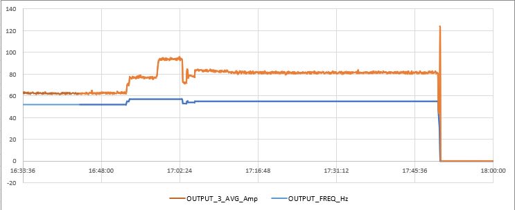
I tried to measure the current and voltage of an induction motor driven by a VSD. The measurement was taken at the input of the VSD, and the results are as follows:
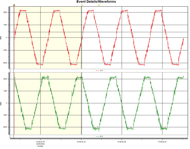
Voltage:
Picture1_ov3fxf.png


Current:
Picture2_nzrupq.png


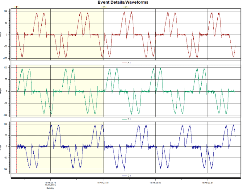
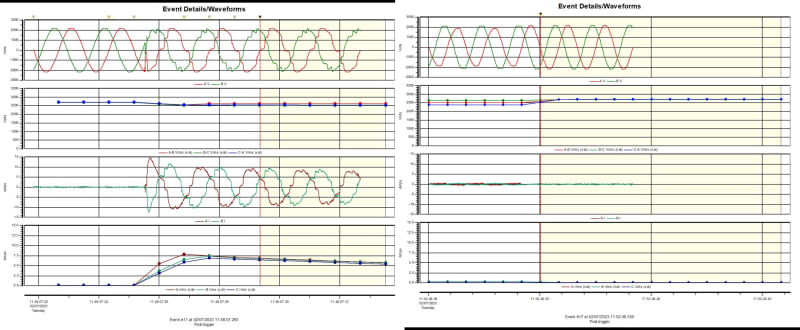
The waveforms are heavily distorted, especially the current waveform. Is this normal? Could it be caused by harmonic distortion? Note that the voltage waveform also appears distorted even when the motor is not running.

Thanks,
Angga
 
Replies continue below

Recommended for you

You appear to be looking at the source side of a six pulse rectifier. That's what many VFDs use.

I’ll see your silver lining and raise you two black clouds. - Protection Operations
 
All inverters will have some amount of distortion on both the input and output sides. How much is dependent on how the electrical current/voltage is filtered. Some of the distortion results from the switching action within the inverter, and some is a result of the impedance mismatch between source (inverter) and bus (for input side) and/or load (for output side). There is no definitive tie between the input harmonic content and the output harmonic content that applies across the board.

As to why there might be input harmonics on the voltage waveform when the motor is not turning - it depends on the drive setting. Is it truly OFF - or are you set to ZERO SPEED? For example, at zero speed, the current is fluctuating to hold the rotor in position.

Converting energy to motion for more than half a century
 
The current waveform looks typical for a VSD. Very high levels of distortion are typical for current waveforms.

The trapezoidal voltage waveform looks quite strange since voltage distortion values are usually fairly small. Is the supply coming from a utility source?
 
Thank you all for your input. To give more context, here is the measurement diagram. DRANETZ is the power quality analyzer:
Picture2_h9fi1d.jpg


In response to your questions:

Yes, the distorted voltage is not when the VSD is truly off, but when the motor is set at zero speed. Please see below the voltage waveform at the moment when the VSD switch is turned on:
21212_vvpbuq.jpg

The supply is not from the big power grid, but we have an isolated power grid consisting of around 12 GTGs.

Zlatkodo,
Yes, it does have a soft starter, but it is not shown on the drawing above. The transformer schematic is like this:
qwqwq_nntnm2.jpg


Could you please explain how exactly the soft starter distorts the voltage waveform?
 
Ultimately it distorts the voltage by distorting the current. Your weak supply doesn’t help matters much.

I’ll see your silver lining and raise you two black clouds. - Protection Operations
 
So initially, we conducted measurements because this VSD kept tripping with the indication of "IGBT high temp", the pattern was the same, the motor could run for approximately 24 hours or more, but it would trip with the indication of IGBT high temp.

We have checked the VSD's cooling fan unit and other items according to the manual, but we could not find any problems with the VSD.

Therefore, we tried to measure the voltage and current to observe any fluctuations that might occur. Unfortunately, the waveform during the trip was not captured by the Power Quality Analyzer, and both the VSD and motor control relay do not have the ability to generate COMTRADE files.

The question is, is it possible that this distorted voltage is causing the IGBT high temp trip?
 
Yes, that is possible. Your local generation based power system may not be stiff enough to keep those drives happy. Line chokes (series reactors) might help (or might not), but it sounds like you may be running on the ragged edge. If the conditions that let you get to 24 hours persisted indefinitely you'd probably be fine, so what happens just before the trip (just before being a relatively loose term) that upsets the balance?

I’ll see your silver lining and raise you two black clouds. - Protection Operations
 
I think more details would help to find a response.
What is nominal VSD current value? Is a constant or variable load? Open loop or control loop (what kind of control loop)?
What motor type and nominal power/current/speed?
Ambient temperature, VSD input voltage, output current, IGBT temperature, motor speed before trip?
Such distorstion are somehow "normal" for any device with standard rectifier (diode + capacitor).
Most probable voltage grid is much below nominal value (but above undervoltage trip), VSD output voltage is below nominal (maybe application request motor at full speed / full load or near), so motor request more current, so IGBTs currents are higher too (maybe close to overload settings).
Higher IGBTs current mean higher losses and for same ambient temperature and cooling conditions lead to higher heatsink temperature.
 
Wait, you have a reactor type soft start ahead of the VFD? Why? Is that left over from an older controller? If so, I would remove it. It does no good for the input of a VFD and will only introduce problems.

The “camel hump” current distortion waveform is absolutely classic for a 6 pulse VFD, or any other non-linear diode bridge rectifier based power device. The flat topping of your voltage waveform is indicative of a weak power source feeding a non-linear load. The diode bridge charges the DC bus by drawing current only at the peaks of each sine wave. After the initial power up sequence in which there is a current limiting system to pre-charge the DC bus softly, the capacitors on the bus will attempt to pull power from the source at the available fault current. In a locally generated system, that can affect the AVR to cause flat topping of the voltage waveform. A line reactor ahead of the VFD is one way to help mitigate this effect because it slows the rise time of the current pulses going into the bus. You also likely do not have a DC bus choke on that drive either, that would help too. Both in concert is the best.


" We are all here on earth to help others; what on earth the others are here for I don't know." -- W. H. Auden
 
Thank you all for your responses. Here is the event record of the recent IGBT Over Temp trip that was recorded by the VSD:

event_uw9i2w.jpg


The VSD was able to record some parameters with a sampling time of 5 minutes. Below is the trend prior to the IGBT over-temp trip. The trend for the events is quite similar. From the trend, it seems like the voltage was constant (referring to the DC bus voltage):

trending_rznjni.jpg


The load is an ESP oil pump, which I think can be considered a variable load. The motor's FLA is 82 A at 60 Hz. The control is an enhanced V/f closed-loop control. The VSD rating is 440 kVA (3 PH, 1400-2500 V, 105 A).
The soft start reactor is the old control, VSD unit was added later

Note:
The speed was kept at 52/53 Hz because the motor current rose up to 90 A when we tried to increase the frequency to 60 Hz
rise_hnltxg.jpg
 
So you have a 2400V VFD that is 6 pulse and running from on-site generation? I know that ESP operations are notoriously “cost conscious”, but that’s somewhat ridiculous in my opinion. MV drives should almost always be at least 18 pulse or Active Front End to keep harmonics under control. I think the burden this is putting on the generation system is the likely culprit behind your problems here.


" We are all here on earth to help others; what on earth the others are here for I don't know." -- W. H. Auden
 
I have checked, and confirmed that the VSD is using a 6-pulse rectifier

The use of VSDs is actually relatively new in our field, and harmonics have never been a concern, so there are no company regulations regulating VSDs and the harmonics generated by loads, especially VSDs.

What standards can we use as a reference for regulating the harmonics on an isolated power grid?
 
You can still use IEEE - 519


" We are all here on earth to help others; what on earth the others are here for I don't know." -- W. H. Auden
 
Yes, but 519 applies at the utility-customer interface, does that even exist here?

I’ll see your silver lining and raise you two black clouds. - Protection Operations
 
No, but one could use it as a reference for what is tolerable.


" We are all here on earth to help others; what on earth the others are here for I don't know." -- W. H. Auden
 
Both trip records was at about same time... may be something related with this that interfere with cooling?
VSD current is much below nominal so temp trip reason may be excesive ambient temp, insufficient cooling, too high VSD switching frequency, IGBT snubbers damage or important harmonics in IGBT - motor circuit.

These tripping arised suddenly or more and more frequently?
What length is VSD-motor cable and what is VSD switching frequency set?

 
After the two previously mentioned trip events, there was another trip event due to IGBT over temperature.
This VSD unit was installed only at the end of last year and has never been run for a long time. The problems varied. Initially, there was a high running ampere as previously described ("the speed was kept at 52/53 Hz because the motor current rose up to 90 A when we tried to increase the frequency to 60 Hz"), and lastly, the problem was the repetitive IGBT hot temperature issue.

The problem of high motor current even though the frequency has not reached 60 Hz has not been resolved yet.
What can be analyzed from this incident?
We suspected that there was a motor voltage supply mismatch. Some important notes regarding voltage are:

[ul]
[li]Motor nameplate voltage is 2736 V.[/li]
[li]SVC (surface voltage calculation), motor voltage + voltage drop = 2813 V.[/li]
[li]VSD voltage rating is 2600 V.[/li]
[li]Because the VSD voltage rating is only a maximum of 2600 V, the VSD supplier recommended that the transformer voltage supplying the VSD be set around 2700 V.[/li]
[/ul]

The cable length from the VSD unit to the motor is 3413 ft, and the VSD switching frequency is 1.6 kHz.
 
Status
Not open for further replies.
Back
Top