Continue to Site

Eng-Tips is the largest engineering community on the Internet

Intelligent Work Forums for Engineering Professionals

  • Congratulations GregLocock on being selected by the Eng-Tips community for having the most helpful posts in the forums last week. Way to Go!

VSD Current and Voltage Input Measurement 1

Status
Not open for further replies.

anggapra

Electrical
Jun 28, 2018
29
Hi,

I tried to measure the current and voltage of an induction motor driven by a VSD. The measurement was taken at the input of the VSD, and the results are as follows:

Voltage:
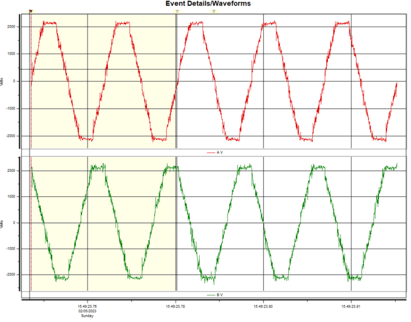
Picture1_ov3fxf.png


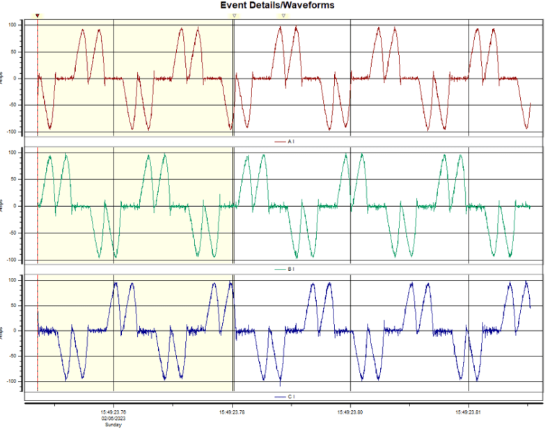
Current:
Picture2_nzrupq.png


The waveforms are heavily distorted, especially the current waveform. Is this normal? Could it be caused by harmonic distortion? Note that the voltage waveform also appears distorted even when the motor is not running.

Thanks,
Angga
 
Replies continue below

Recommended for you

There is an important difference in voltage... more than 10% that mean more than 20% in motor torque.
Motor have not enough voltage/torque,so when you try 60Hz VSD output, motor current increase above nominal and can't reach desired speed.

At about 1km cable there are problems with capacitive currents, voltage increase and dv/dt that may affect motor isolation and create VSD overstress; need to add output reactors and maybe output filters.

What's values for motor base frequency and motor voltage parameters in VSD?
 
Your VFD is one size too small and one voltage level too low.
You appear to be running on the ragged edge of full load motor current.
A higher voltage would help lower the current at a given Hz.

I don't see mention of an output filter. Did I miss something?
A quick google search on "VFD cable lengths" indicates that filters are recommended for lengths exceeding 80 to 100 FT, depending on the site.
In some SAGD pads that I visited, they used one of two different mitigation techniques.
Some pads used 4160 Volt VFDs and a large filter adjacent to the VFD.
Other pads used a 4160 Volt VFD and a 4160/600 Volt transformer to run 600 Volt submersible motors.
Our work consisted in inspecting and bringing the grounding up to code minimums.
Despite my interest, I was unable to gather any information comparing the relative effectiveness, efficiency and cost of the two mitigation methods.

What is the nominal head that your ESP is pumping into? What is the maximum difference in discharge head, relative to the nominal head.
Valving from a full tank to an empty tank may increase the dynamic head and the motor current. This may happen faster than your PID control can stabilize, causing an overload, heat related trip.
Any surface condition that reduces the dynamic head may cause an over load.


--------------------
Ohm's law
Not just a good idea;
It's the LAW!
 
Status
Not open for further replies.

Part and Inventory Search

Sponsor