Eng-Tips is the largest engineering community on the Internet

Intelligent Work Forums for Engineering Professionals

VSD or throttle control strategy for RO High pressure pumps 1

Status
Not open for further replies.

baasi

Mechanical
Jul 14, 2016
28
0
0
PK
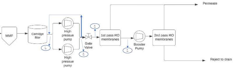
We have two stage RO plant of capacity 75 m3/h (permeate)[/color] and two high pressure pumps(51 m3/h each) are installed to maintain the feed flow. The raw water flowrate is 94 m3/hr . The throttle valve flow control strategy is applied along with the bypass. The whole scenario is shown in attached picture.
Note : Membranes type is CPA3 Hydranautics
High pressure pumps are vertical multistage centrifugal pump with 37 KW rated capacity motor.

Some of the parameters are as follows:
1- Inlet pressure of the High pressure pumps is 2 bar
2- Outlet pressure of the High pressure pumps when both are running in parallel is 20 bar
3- Pressure after throttle valve is 15 bar which means requirement of the membranes is 15 bar
4- Pressure drop after first stage of RO is 12 bar
5- Booster pump boost the pressure to 15 bar again for 2nd stage RO.

I have some questions related to it and would appreciate the reply from experts.

1- What throttle valve actually do? Does it control pressure or flow?
2- As mentioned above the pressure requirement for the membrane is 15 Bar but the pumps are generating 20 bars. Why do we need pumps or higher pressure and flow?
3- Would it be feasible/worth it to install VFD on one pump and other pump will work on fixed speed.
4- Do you think pump are sized properly?
RO_r6vdct.png
 
Replies continue below

Recommended for you

Just a note about using colored text in your postings. Some people are color blind and when you have a colored background and colored text, they are unable to differentiate between them. I am one of those people and I can't see the text after "capacity" or "pumps" in your first sentence, nor the text in the other sentences.

Thanks.
 
Yes the coloured text is very difficult to read - why did you do it?

Anyway


1- What throttle valve actually do? Does it control pressure or flow?
It looks like it is set up to control pressure, but your diagram is not easy to read and is a bit simplistic - A P&ID would tell you more

2- As mentioned above the pressure requirement for the membrane is 15 Bar but the pumps are generating 20 bars. Why do we need pumps or higher pressure and flow?
Not easy to say, but it's always good to have a bit spare. Also probably means one pump could do 60-70 m3/hr and still make 15 bar.

3- Would it be feasible/worth it to install VFD on one pump and other pump will work on fixed speed.
Can't see this being worth it

4- Do you think pump are sized properly?
yes.


Remember - More details = better answers
Also: If you get a response it's polite to respond to it.
 
Since the goal of this system is to make 75m3, and it is believed that it will take 94m3 at 15bar when the system is new.
What will it take when feed temperature or quality changes? What about when the membranes foul?
Having capacity to develop 102m3 at 20bar is likely to assure that over time the output can be maintained.
Since the pressure will fall as the square of the speed there isn't much room for a VFD to adjust.
I wouldn't bother.

= = = = = = = = = = = = = = = = = = = =
P.E. Metallurgy, consulting work welcomed
 
The pumps will not generate 20 bars unless the system has 20 bars of resistance.
You are losing 5 bars of pressure in that gate valve and the little bit of piping around it.
Assuming the gate valve is full open, all of those things there need to be a larger diameter.
You should only have 0.5 bar, maybe 1 Bar absolute maximum, loss there. You have 5? WAY too much.

Your effort is probably best spent in reducing pressure loss. If you can increase the size of pipe and valve and the pump still produces too high a pressure for some reason, reduce the size of the impeller.

VFD basically helps the most when you need to run at highly variable flow rates. If you have mostly a uniform flow rate, rework of the pump will probably be better.

It would help to know the flow range you need to run through this system and at what flow rate you get the 5 bar loss at the gate valve.

Einstein gave the same test to students every year. When asked why he would do something like that, "Because the answers had changed."
 
The output of the pumps will be dictated by the system, not the rating.
Where the system curve and pump curve intersect will be the operation point.
You won't be trying to pump 20bar unless you have that much restriction.

= = = = = = = = = = = = = = = = = = = =
P.E. Metallurgy, consulting work welcomed
 
@EdStainless, @1503-44, @LittleInch,@coloeng, Thanks everyone for your great replies. My apologies for coloring some of the text in my post, will be conscious text time.
As from your replies I am making conclusion that VFD is not a feasible solution here because flow remains almost constant. I know that 20 bar flow at the outlet of the pump is because of this throttling mechanism, if the restrictions are not there pressure would not be that high. Probably it would be 15 bar as required in for the operation of the membrane.
I have some follow up questions here:
1- Is there any way to make a case that VFD is not a suitable solution for this case? I have to present this to higher management so there should be a solid reasoning behind it. Currently for the above discussion I am unable to say it clearly.
2- Is there any correlation between motor power and pump outlet flowrate?. We have another pump of similar power i.e. 37KW and its rated flowrate is 155 m3/hr but here in above mentioned case, for the same power it is 51 m3/hr.
3- What is the relationship of permeate production with the pressure and feed flow? Like for example to produce 75 m3/hr of permeate how much should be the feed flow?
4- I have two proposed solutions in my mind, please comment if those works:
- First solution is to fully open the outlet valve and operate one pump at fixed speed and one at VFD.​
- Second solution is to install two pumps of 100 m3/hr and operate only one at fixed speed. The other pump would be at standby​
 
First some theory

Pump Power = Flow_rate x Density x Head / pump_efficiency

VFD or Constant speed (CS)

VFD generally makes operating a pump at any flow rate more economical. constant speed (CS) pumps operate efficiently near their BEP flow rate. BEP is Best Efficiency Point. Efficiency of CS is generally reasonable within +/- 15% around the BEP flow rate. If your flow will always be in that range, do not think of using VFD, use CS with a valve to control flow.

VFD does not produce much pressure below 50% of pump rated flow. If you need a constant pressure, again use CS. If low pressure at low flows is acceptable for your system, then VFD may be useful.

COMBINING CS and VFD (generally not good)

Say the (CS) pump is running at its best efficiency point. Operating one pump at CS and the other with VFD will basically require matching the pressure produced by the CS with the VFD controlled pump. If the VFD does not match the pressure of the CS, the CS flow and pressure will move away from its best efficiency point. That will negate the advantage of having the VFD controlled pump. How bad that will be depends on how far away the CS flow rate is from its Most Efficient point. Over 25% away from best CS operating point will probably destroy any good reason to have a VFD at all, since the CS will be operating at a flow rate with much poorer efficiency.


--Einstein gave the same test to students every year. When asked why he would do something like that, "Because the answers had changed."
 
1) You must compare the potential savings between the two control systems using the efficiency and pumping cost. Basically the more your system flow rate varies away from BEP, VFD operation can be cheaper. If you spend a lot of time running low flow rates, especially below 50% AND you do not need a lot of pressure at low flow rates, VFD control can be a very good solution. If one, or the other of those is not true, think CS-valve control.

Operating cost can be calculated at various flow rates for both CS and VFD cases. Find out at what flow rates the CS is cheaper to operate and at what flow rates the VFD is cheaper. Decide how much time will be spent operating at each flow rate, how much power is required and add up the resulting operating costs of each option.

2) see the theory above for power relationship. The difference in power is caused by bad pump efficiency. You are trying to operate at a flow rate where the pump[pre][/pre] efficiency is relatively very poor.

3) I do not know anything about that.

4).Yes. Open that valve full.
I would not install VFD just yet. You said your flow rate does not vary much, so initially VFD is not a good idea to start with. You should first try to match your pumps to the most typical flow rate and use CS.
Having one or two pumps with standby is a maintenance question that does not affect the VFD/CS decision.

It appears that CS with a valve will be the best solution for another reason too. That's what the first group of engineers also thought when they designed your present system. Think long and hard before changing the basic original plant design concept. It probably just needs a "tuning up". This IMO is very important.

--Einstein gave the same test to students every year. When asked why he would do something like that, "Because the answers had changed."
 
The balance between production and rejection (or total flow) is related to the membranes.
Yes, pressure is a factor. But so is how clean they are and the temperature and a few other factors.
You don't want to run two pumps in parallel with them operating at different speeds.
They will make different head and one pump will be running far back up the curve, not good.
I would have built this system with 3x50% pumps for some backup.


= = = = = = = = = = = = = = = = = = = =
P.E. Metallurgy, consulting work welcomed
 
baasi,

You're doing this the wrong way around. You need to look at the requirements of the membranes, their long term pressure requirements over time etc. you need to talk to the RO supplier.

Only then can you try and figure out what pumping is required.

VFDs simply do not work effectively when you have a fixed pressure and very little flow change.

The VFDs cost money and also use about 8% of the power going through them. Mr 44 has given you lots of good information.

In reply to your points.
1) It's difficult to prove a negative. Just look at a set of options and then compare them using CAPEX, OPEX and "operability". OPEX for VFDs don't forget the losses in the VFD itself.
2) see reply from mr 44. All other things (e.g efficiency, fluid) being equal, power is proportional to flow x differential head. Same power, more flow, lower differential head assuming efficiency are similar
3) RO membranes are strange things and don't always follow more pressure = more flow. Also they have potential to burst. Fouling over time results in higher pressure for the same flow. Talk to the RO people.
4) You talk about a "solution", but for me you haven't actually defined the problem. A said I think you're jumping to conclusions and I don't know why this is seen as a "problem" that needs fixing??

Remember - More details = better answers
Also: If you get a response it's polite to respond to it.
 
Your drawing appears to be an error. Where did you get the drawing?

RO systems generally operate at constant flow so you would never have a variable speed pump.

A regulating valve is installed on the RO reject side to control the back pressure across the membranes.

Manufacturer's usually supply the RO equipment as a system. Talk to a manufacturer.

See typical flow diagrams:

RO Diagrams
 
Color overload.

--Einstein gave the same test to students every year. When asked why he would do something like that, "Because the answers had changed."
 
I don't understand your diagram. Can you provide a P&ID?

If not: The blue arrow behind the pumps represents a pressure regulator / bypass?
Is the throttle valve manually adjusted so that 15 bar, or what?
The gate valve is just a passive component without control function?

How long is/was the system in operation? Always 15bar on the membranes, or sometimes more? Have you talkend to the operators?

20bar is nameplate capacity of the pumps, do you know the actual pressure after the pumps?

I understand your problem so - the question "VFD or not" landed on your desk. I think the root question, or problem to solve, is the energy consumption of the system.

As others have said: find out what the RO system needs why the large pumps where installed. Seriously consider reworking the pumps for a lower pressure (that involves removing a bit of impeller material in a lathe and the manufacturer of the pump should be able to do it)
 
@MartinLe, thanks for your reply. I really appreciate your time.
Unfortunately I do not have P&ID, that is the only diagram that I have.
- Yes the blue arrow behind the pumps represents bypass​
- Yeah throttle vale is manually adjusted then the pressure after the valve is 15 bar​
- basically it is not a gate valve, infact it is globe valve who is manually adjusted​
This system is in operation since 2017 and pressure always remains 15 bar on the membrane. I am not sure about the nameplate capacity of the pumps since they do not have nameplate but this 20 bar is the actual pressure of the pumps when both are in operation.
Thanks for understanding my real concern which is whether to recommend VFD or not.
I would recommend reworking of the pumps once I will be quite sure that it is needed and for that I need expert opinions
 
Unless you need to keep a lower pressure on the membranes then is being delivered by the pump, you should be controlling the system pressure with a backpressure control valve downstream of the membranes, IMO.

SO, I would try these steps.

Try opening the globe valve to drop system pressure.
If you get too much flow across the membranes, or the pressure drops too much, try an increase in the whole system pressure again, but this time with a new valve downstream of the membranes, while opening up the existing globe valve fully.
If the system pressure is still too high, then trim the pump impeller to get flow and pressure on the mark.
If that looks good and the pump is on the mark, then keep the new downstream backpressure control option and pull out the existing control valve. Maybe that could be moved to be used as the downstream backpressure control valve.

--Einstein gave the same test to students every year. When asked why he would do something like that, "Because the answers had changed."
 
I would use a pressure reducing type valve in place of the "gate" globe valve being used. Setting the pressure reducing valve to deliver 15 bar to the membrane will maintain 15 bar pressure by varying the flow to match the demand.
 
It isn't a gate. A globe is fine.
But it does add unnecessary pressure to the system where it is now.

--Einstein gave the same test to students every year. When asked why he would do something like that, "Because the answers had changed."
 
No different than the gate valve being used now, a pressure reducing valve would only add extra pressure to the high pressure pumps, not the system. The extra back pressure on the pumps is needed to keep them from pumping more water than the RO demands. By setting it to maintain 15 bar pressure the pressure reducing valve will match the flow needed by the RO. The extra back pressure on the pump will reduce the amperage and make the motor run cooler.
 
Status
Not open for further replies.
Back
Top