Eng-Tips is the largest engineering community on the Internet

Intelligent Work Forums for Engineering Professionals

  • Congratulations waross on being selected by the Tek-Tips community for having the most helpful posts in the forums last week. Way to Go!

VSD

Status
Not open for further replies.

Guardiano

Electrical
Nov 11, 2008
118
0
0
MU
Dear forum members,
I am having an issue with a 400 k W pump. The pump is driven by a variable speed drive.When the pump is started, it ramps well to rated speed and the current on the three phases are very well balanced at nominal speed. The pump pumps well and there is no issue with the pump pressure. However, as the pump is started, the potential to ground rises and even reaches phase to phase voltage. My first guess was that the neutral on the supply transformer was floating but this was checked and found to be correct. A second pump, rated 200 k W, on the same transformer but DOL starting does not give any potential to ground problem. I have checked the VSD but with the motor disconnected, the VSD ramps to 5o Hz and the phase to ground voltage is very stable and does not rise. I have also meggered the motor and the results are very satisfactory, almost infinity to ground on the three phases. The supply voltage is 400 V and the transformer is rated at 3 MVA and is solidly grounded.
Any advice?
Thanks
Guardiano
 
Replies continue below

Recommended for you

Yes, where are you measuring this and with what?


" We are all here on earth to help others; what on earth the others are here for I don't know." -- W. H. Auden
 
Dear Waross and Jraef,
I'm measuring the potential to ground on the incoming supply to the pump. We did also measure on the LV side of the transformer too. Both sides showed a rise in the potential to ground voltage.
I'm using an industrial true RMS meter, Fulke 87, for this purpose.
Thanks.
Guardiano
 
You've checked everything well. VSD and meggered the motor.
What is likely happening is your very high input impedance Fluke is measuring the capacitive leakage caused by a large motor being fed by high voltage, high current, high frequency power. The capacitance inherent in the motor construction, where there is lots of wire close to the housing or the rotor and it's driving the motor housing. The Fluke see's this and even though it is too little current to do much the Fluke can measure it.

I would use a neon tester like this one or similar to check from the motor case to earth.
Amprobe PY-1A Voltage Tester

This style tester significantly loads the source and if it's capacitive in nature you will see a large difference between the Fluke and the neon tester. Hook the fluke up and while watching it use the neon tester. If it's capacitive, like I suspect it is, the Fluke reading will plummet.

A follow up test would be to change the modulation frequency of the motor with the Fluke hooked up and untouched. Again, if it's capacitive you will see a substantial change in the reading between modulation frequencies because the leakage impedance is:
X[sub]c[/sub] = 1/(2ΠfC[sub]leakage[/sub]) If you raise or lower the modulation frequency you will affect the leakage.

Typically problems with this are best resolved by connecting the motor casing back to the VSD factory grounding point. You have to do this with a conductor that can carry high frequency current effectively. That means it should be have lots of surface area. But do some more checks before doing better grounding.

Keith Cress
kcress -
 
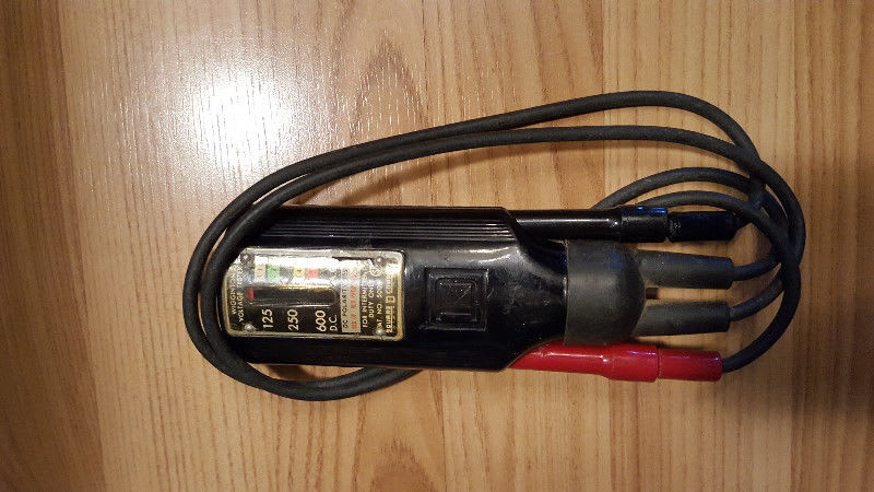
Better yet use a Wigginton Voltage Tester. AKA "Wiggy"
_59_yumg1i.jpg


Bill
--------------------
"Why not the best?"
Jimmy Carter
 
Bill, almost every time I mention using a Wiggy (or its sister, Knopp) lately I get blank stares from anyone under the age of 50... they have no idea what they are (were). Fluke (and their offspring) have effectively removed them from the vernacular it seems. Pity.


" We are all here on earth to help others; what on earth the others are here for I don't know." -- W. H. Auden
 
It's on Wiki under Solenoid voltmeter, Jeff.
George Wigginton patented the Wiggy 100 years ago.
Wiki said:
Solenoid voltmeters are extremely rugged and not very susceptible to damage through either rough handling or electrical overload.

For "go/no go" testing, there is no need to read the scale as application of AC power creates a perceivable vibration and sound within the meter.This feature makes the Wiggins tester very handy in noisy, poorly illuminated, or very bright surroundings. The meter can be felt, the more it jumps the higher the voltage.

Solenoid voltmeters draw appreciable current when operating. This makes them useful for testing residual-current devices (GFCIs) because the current drawn will trip most RCDs when the solenoid voltmeter is connected between the live and earth conductors. Also, when testing power supply circuits, a high-impedance connection (that is, a nearly open-circuit fault such as a burned switch contact or wire joint) in the power path might still allow enough voltage/current through to register on a high-impedance digital voltmeter, but it probably will not actuate the solenoid voltmeter. For use with high impedance circuit applications, however, they are not so good, as they draw appreciable current and therefore alter the voltage being measured.
I saw one in a tool crib a couple of years ago, but no-one knew what it was.


Bill
--------------------
"Why not the best?"
Jimmy Carter
 
I used to own a couple of them. I haven't seen either of them for more than 20 years.
One advantage, when working on a Ward Leonard panel with a mix of AC circuits and DC circuits, you knew instantly by the feel of the Wiggy if you were on an AC or a DC circuit.
I haven't seen a Ward Leonard for a lot more than 20 years.

Bill
--------------------
"Why not the best?"
Jimmy Carter
 
Status
Not open for further replies.
Back
Top