Continue to Site

Eng-Tips is the largest engineering community on the Internet

Intelligent Work Forums for Engineering Professionals

  • Congratulations KootK on being selected by the Eng-Tips community for having the most helpful posts in the forums last week. Way to Go!

W Beam set on top of HSS 1

Status
Not open for further replies.

BrianApex

Structural
Jan 22, 2015
7
I was wondering if there were any design aids for setting a steel beam on a steel post. I would think this should be possible but there is nothing provided by AISC (At least that I could find). I have also searched in here to see if someone mentioned it but I couldn't find anything. My thinking was to have the beam rest on a plate welded to an hss column and add a stiffener at the end of the beam if needed.

I have a 38 foot W21x121 Beam that has a extended end plate to a W14x90. This is for a residential house and it's kind of bulky and would rather use a hss column if possible. This is used as a moment frame as well as a header for a 32 foot opening.
 
Replies continue below

Recommended for you

The cap plate connection may not achieve what you have in mind - moment connection. It is fine for interior supports.
 
Look a little harder!..,AISC 360 15th edition pg. 12-26. I'm sure this is in at least the last few editions as well under FR Moment Connections With HSS (don't have those on hand right now).

I also know I've seen some threads about this specifically on here.

Also...W21x121 for a residential house! Wow! Must be some kind of megamansion :O
 
I've often connected W Sections to an HSS with a thick top plate to transfer the moment... not a real big problem as long as you have the real estate for the connection.

Rather than think climate change and the corona virus as science, think of it as the wrath of God. Feel any better?
-Dik
 
strucbells:
I have seen this as well as the design Guide 24 which has a very good explanations and example of how this works. My only issue is that my column would be at the end condition and not an interior support. I dont see anything which mentions an end support and wasn't sure if I could carry over the same methodologies or not.

Also the reason for the giant beam is only for deflection. The beam isn't even close to failing but there is a 32' sliding glass door system and I'm just worried about it binding. Not really a mega mansion but its on the water so they want a huge view of the water.

dik:
I was just worried that there was something that I was missing because I haven't seen examples of this specific connection.
 
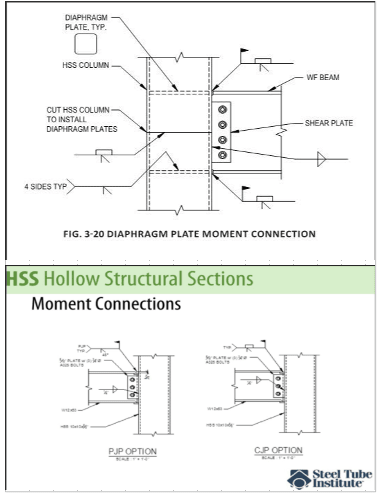
Two examples for your information. Check STI for guidance.

image_o89xup.png
 
BrianApex said:
I have seen this as well as the design Guide 24 which has a very good explanations and example of how this works. My only issue is that my column would be at the end condition and not an interior support. I dont see anything which mentions an end support and wasn't sure if I could carry over the same methodologies or not.

I was getting ready to mention the Design Guide for HSS connections (DG 24). Yes, the same methodology holds. The only question is that if the beam is terminated within a certain distance (d/2?) of the column then some of the checks (Web Local Yielding, Web Local Crippling, Web Compression Buckling). But, most of this is spelled out in J10.6 of the specification. Essentially, you follow the same procedure with the same concepts, but some of the capacities get reduced a bit.
 
r13 -

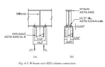
I could be wrong. But, I think the OP is talking about a connection that looks a little more like the following (where the column terminates just below the beam rather than continuing past). Though he also said the beam ends at this connection too. So, your connection could still work with the column continuing up a bit with a cap plate at the TOS location of the beam flange.

image_ifspbq.png
 
Josh,

Yes, you have miss read the OP's latest response. In which he says "My only issue is that my column would be at the end condition and not an interior support." And, I think he needs clear span for the view through the long glass door.
 
You can still have a column cap connection at the end of the beam... with the beam over the top of the column. That's what I think the OP was talking about.

I took his "my only issue" comment about the column being at the end condition to mean that the connection I showed is slightly different than he wanted to use because the one I showed had a continuous beam. But, the concepts are the same.

Note: I would not use the connection I showed as a SMRF or IMF for seismic. But, I would think it would be fine for moment resistance of gravity loads.
 

Not missing much... not common, but I've done it... Thick, designed cap plate and beam plate with an end plate welded to the HSS and beam plate, and two 'wing' plates at the front edge of the beam plate to keep the HSS wall from collapsing. Welds transfer the moment from the HSS to the beam plate and bolts transfer the moment to the cap plate... I'll see if I can dig up a CAD dwg...

Rather than think climate change and the corona virus as science, think of it as the wrath of God. Feel any better?
-Dik
 
Since it needs to be part of a moment frame - I would recommend framing the beam into the side of the column and using a moment connection. We commonly do the detail that Dik mentioned with big strap plate from the top of beam to the top of the column and then a angle seat at the bottom flange to take the moment.
 

I like your detail, Josh... use it often and I like the web stiffener terminating an inch or so below the top flange... I still see a lot of projects where they fill the web space (except for the fillets)... easier to fit, less material and weld... it's a win-win.

Rather than think climate change and the corona virus as science, think of it as the wrath of God. Feel any better?
-Dik
 
r13:
Sorry, My explanation may have not been clear. Josh is correct with my problem.

dik:
Thanks, That is very helpful. But may not be necessary. After switching to the smaller HSS and running the beam it increased the deflection (duh) too much and I will have to switch back to what I was using before with the W beam running into a W beam column.

8th Street:
I don't have any issue with attaching to the side but my assumption was that the column width would have to be the same or wider than the beam itself. In addition, I think its easier for the contractor, they wouldn't have to bring a welder to the site and it would be easier for them to bolt it then weld. but as I mentioned earlier it doesnt matter no as i have to switch back.

Thanks everybody for your help. I greatly appreciate it.

 
Not a problem. I've expressed my view on my original response concerning the long span, and end column situation. My second response was meant to introduce STI as a source of ideas, if you insisted to carry out the design as proposed. I shall offer my apology to Josh, as I didn't read/understand his response properly, so literally I've miss read you and Josh both :)
 
r13 -

No need for an apology. I misinterpret posts as often as anyone else. As long as we don't "hate on each other" for interpreting something differently we'll always be okay.

Also, I think the reference towards STI (Steel Tube Institute) is excellent. They give a lot of good support to engineers. Lastly, I think a variation on the connections you showed connections would have worked fine as well. Arguably they could be a little better if we're concerned about connection rigidity.
 
Josh,

Thanks for your understanding, and taking time for further clarification.
 

No, I'm better at it...


As a member you have access to several very good technical webinars...

Rather than think climate change and the corona virus as science, think of it as the wrath of God. Feel any better?
-Dik
 
Status
Not open for further replies.

Part and Inventory Search

Sponsor