Continue to Site

Eng-Tips is the largest engineering community on the Internet

Intelligent Work Forums for Engineering Professionals

  • Congratulations SSS148 on being selected by the Eng-Tips community for having the most helpful posts in the forums last week. Way to Go!

Wall of Windows 2

Status
Not open for further replies.

medeek

Structural
Mar 16, 2013
1,104
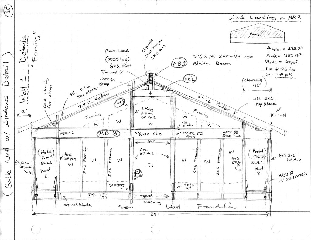
I've got a wall of windows on a gable end with possibly two methods of framing it (so far). Can anyone tell me what is wrong with the first picture? Note that 22 ft. of roof is tributary to to the glulam beam at the ridge (actually only half of that 11 ft is tributary to the gable wall). The load is the S + D, the dead load is approximately 50% of the total load.

2014-017_WALL1_REV1.jpg


2014-017_WALL1_REV2.jpg
 
Replies continue below

Recommended for you

With the first picture, the 5.125 X 12 glulam will probably fail in wind weak axis bending. lateral deflection will be a lot more too.

I much prefer the second option with the two full height columns taken to the roof diaphragm.

Mike McCann, PE, SE (WA)


Option one lacks post continuity from foundation to roof diaphragm. You'd either need a monster girt at eave hight or you'd have to count on the specified strapping to moment connect the posts across the girt. Using the straps in this way would make me particularly nervous as the substantial load from the ridge girder will tend to promote stability problems.

Have I passed the quiz?

The greatest trick that bond stress ever pulled was convincing the world it didn't exist.
 
I made it too easy, I shouldn't have posted the wind load information on the first sketch.

With the 189 plf load on the glulam beam in its weak direction, neglecting any straps that may counteract this lateral load, even sistered with two 2x6 (top and bottom) I get the following:

fb = 4500 psi > Fby' = 2530 psi (CSI = 1.78) ======> NG

Also if the beam doesn't snap it will deflect 15.2 inches. Granted the wall may act as a web to some degree and resist this lateral deflection but I wouldn't count on it.

Then you take the vertical loads which will only make matters worse (hinging effect).

Hence Rev. 2 of the design... and I need to explain to the architect/designer why his wall of windows won't work.


Could you run the two 6x6 posts through continuously, and get rid of everything else other than the eave hight girt and the shear walls?

The greatest trick that bond stress ever pulled was convincing the world it didn't exist.
 
My biggest concern with option #1 (besides the obvious deflection issues with the Glulam) would be the connection at the two shear walls.
The load coming out of both ends of the Glulam would be in the range of 4,000+ lbf - not your average wind load.

A quick glance at your Second drawing (much better design in my opinion) gives me concern about the 2x12 rafters.
Tall gable end walls always need special concern for the lateral support at the roof decking.
I would frame the wall full height to the roof decking and attach a 2x4 or 2x6 ladder spanning at least 24" (your first roof truss / rafter past the wall), possibly 48" depending)
The Ladder framing runs at 12" OC. perpendicular to the wall with:
-nails to the roof decking to transfer lateral load to the diaphragm
-nails to the double top plates to transfer load to the ladder framing
-this allows you to cant out for overhang as well


See the attachment for a similar design I have done - pay attention to the lower right hand for the ladder framing detail
 
 http://files.engineering.com/getfile.aspx?folder=74986ed0-4b55-4783-aafb-3915f368988d&file=ladder_framing_detail_(full_ht_tall_gable_wall).pdf
I see where you are going with this Signious. The 2x12 on edge will want to topple over without some blocking running perpendicular to the rafter.

How about something like this:

GABLE_ROOF_DETAIL_1024.jpg


If more strength is needed put another 2x4 block in line with the outlooker to the next rafter (and strap tying the two together).
 
This will require a nailer on the inside wall for the ceiling sheetrock. Also the straps connecting the 2x12 Header (HD1) to the DBL top plate will require some additional blocking if the strap is on the inside (block as required).
 
The change in the posts shrunk my shearwalls slightly as well as increased the height. At 514 plf I'm going to sheath the interior and exterior of both shear panels and even though my allowable is 670 plf, and probably a little conservative, I welcome the additional margin of safety.
 
Is there any particular name you call the stubby 6x6 post that the glulam beam seats on?
 
Depending on the size of it required a lot of times I would call it off as full bearing solid blocking down to the 2x12 header.

I think it's unlikely that you need the capacity of a 6x6 over a short height like that.
 
Probably not, but it does fit nicely.
 
So does a 3 or 4 ply 2x6 created from the cut ends they will have lying around.
 
@medeek

I usually just call it a cripple post / cripple stud (same as I call the studs below sills)
 
Alright, 4 ply 2x6 with a 1/2" ply spacer. No contractor is going to want to cut up a nice 6x6 post for such a small piece, I see your point. I think most contractors will take whatever shortcuts they can regardless of what the plans actually say.
 
Hey Medeek,

off topic question: where abouts in the world are you, and what is the 'standard' lumber species you use. I see a lot of D.Fir being used, but where I am if you spec anything other than SPF you get a lot of angry calls
 
@medeek;

Those are pretty extensive calcs and sketches. How are you making any money on these jobs?
 
Kick-ass spreadsheets. I doubt Medeek does much of anything by hand more than once.

The greatest trick that bond stress ever pulled was convincing the world it didn't exist.
 
I don't consider the calcs that extensive but the sketches are really for discussion points and my own education. I've never dealt with an exotic wall like this before so I'm chalking it up to "education and new skills". On this particular job I had to deal with custom portal frames and this wall, both of which have taken me over a week just to think through, research and discuss with other engineers on this site and over the phone, as well as by two additional text books. Tomorrow I meet with an old engineering friend of mine who has agreed to peer review the project, his services are not inexpensive either. So I've actually lost money on the job but I've gained much more, created two new computational tools, and now understand the methodology behind analyzing portal frames.
 
Status
Not open for further replies.

Part and Inventory Search

Sponsor