Continue to Site

Eng-Tips is the largest engineering community on the Internet

Intelligent Work Forums for Engineering Professionals

  • Congratulations SSS148 on being selected by the Eng-Tips community for having the most helpful posts in the forums last week. Way to Go!

Wall Penetration Reinforcement 1

Status
Not open for further replies.

SMhc

Structural
Nov 11, 2015
6
Hello,

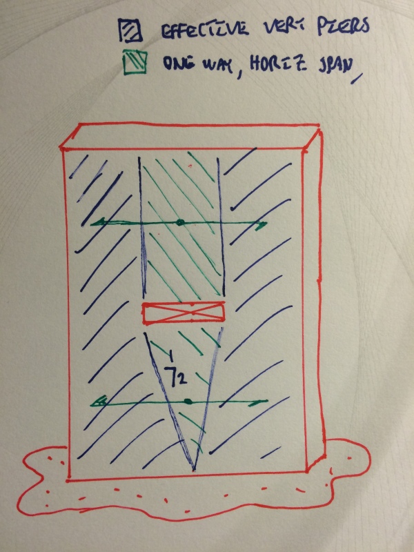
I am working on a 16in thick CIP concrete firewall for a transformer and need to account for a roughly 10' wide by 2' tall penetration about halfway up the 40' wall. Obviously I am concerned with losing 10' of vertical reinforcement and I need to make a force pathway to either side of the opening. I understand the basic premise of providing extra reinforcement as well as corner bars to form a 'force arch' around the penetration.

Previous projects seem to have used software models to determine the reinforcement, however I always like to have a hand calc to go with that as a sanity check. I can take a stab at producing a calc, however I would love to see if you have any recommendations. Can anyone point me to a reference that deals with this situation, or how you have dealt with proof that your penetration reinforcement was sufficient?

Thanks for your time.
 
Replies continue below

Recommended for you

Standard opening detailing probably isn't going to cut it. How much wall do you have on either side? Do you have return walls at the ends?

I like to debate structural engineering theory -- a lot. If I challenge you on something, know that I'm doing so because I respect your opinion enough to either change it or adopt it.
 
It is quite a wide opening, therefore, I would do more than standard extra reinforcement around the opening. I would probably set up a small FEM model of the wall, using all applicable loads.
 
Thanks for the replies. There is about 10 feet on either side before hitting the firewalls that run perpendicular. I was going to show in the calc that additional steel provided along the penetration was sufficient to withstand the bending moment of the wall above the penetration. Just wondering if there's other factors that I am not thinking of.

jike, that's the go to for the people around me as well, and I likely will do this - just wondering if anyone has approached this without a model as I know it's been done. Thanks!
 
Manually, we would probably transfer the load from 1/2 the opening plus a portion of the continuous wall (say 2') to a vertical strip (say 2' wide) and determine the required reinforcement to span full height.

Do a similar thing for the horizontal span.

The FEM model is the simplest and most accurate.
 
Based on your proportions (30WX40H), I'd span the wall horizontally in which case the horizontal opening would become pretty much irrrellevant.

I like to debate structural engineering theory -- a lot. If I challenge you on something, know that I'm doing so because I respect your opinion enough to either change it or adopt it.
 
Jike - That's exactly what I have started to do. Thanks for confirming my thought process. I plan to model it as well.

KootK - I hadn't thought of that. However as windload is governing, I would still need a lot of vertical reinforcement so I'm not sure if that would help. I could be misunderstanding your point.

Slide - You nailed it, it's a main xfmr firewall subject to environmental loadings. wind governs
 
No reason wind load can't distribute through horizontal spans too. I suspect that your FEM model will comfirm horiz spanning as the dominant structural action. Your solid side panels are really in the "flexurally useless" zone as far as vertical spanning goes.

I like to debate structural engineering theory -- a lot. If I challenge you on something, know that I'm doing so because I respect your opinion enough to either change it or adopt it.
 
Oh, I understand. I agree with you if I were designing the wall considering it as a beam between the two other walls. However, I am designing it to be sufficient freestanding in case the owner would like to remove the other walls in the future. I should have clarified that when you asked about the other walls earlier. The model will just have the mat foundation and the one wall with the opening.
 
I agree with KootK's approach. It seems ridiculous to design that wall to be freestanding, and if it is to be cantilevered, 16" is probably not enough.

Using some FEM program to design this wall would solve nothing...you already know there will be stress risers at the corners of the opening.
 
Ah. Then, somewhat similar to Jike:

1) above the opening, treat as two 10' wide wall piers with all loads on the wall segments between spanning out to them.

2) below the opening, you've got enough meat that the load can probably spread back towards the middle. This could be handy as you'd essenntislly be back to a full section in flexure,

I like to debate structural engineering theory -- a lot. If I challenge you on something, know that I'm doing so because I respect your opinion enough to either change it or adopt it.
 
At 40', she is a very tall cantilevered wall. Were I to do it that way, I'd be envisioning something like this.

Tall_Wall_eitfxv.jpg


I like to debate structural engineering theory -- a lot. If I challenge you on something, know that I'm doing so because I respect your opinion enough to either change it or adopt it.
 
Agreed, it's silly to design freestanding. But I don't write the contracts...just making sure it doesn't fall down :)

KootK - thanks for the sketch and your input. Very helpful
 
A little background; there are operational and maintenance reasons for a freestanding wall design:

1. Transformers of this size (several hundred megavolt-amperes) are incredibly efficient, typically over 99.6% efficient. Still, energy loss of 0.4% creates a lot of heat. The transformers are oil cooled, but the oil has to be cooled by fans blowing through transformer-mounted heat exchangers. To maximize heat dispersal, minimal structure near the transformer is essential.

2. The transformer should sit on a concrete pedestal inside a stone-filled concrete pit, top of both the pedestal and pit wall at ground level. The space between the stones provides environmental containment of transformer oil in the event of a leak or failure. The size and location of the pit could make bracing a wall more complicated.

3. The main transformer is a critical point for power generation - there is only one main transformer per generating unit. Transformer failure is rare, but a utility wants quick, uncluttered, and straight forward access to the transformer if a replacement has to be put in service. This point is so important to our company that we purchased a spare main transformer for our largest station. It sits onsite, about 100 yards from the transformer yard, unused but maintained, over it's own dedicated oil containment pit.

The photo below shows a typical main transformer surrounded by the containment pit:

520004da92bba-010111_OM_fig2.jpeg


[idea]
[r2d2]
 
Thanks for that, SRE. And I withdraw my comment about the freestanding wall being ridiculous. We simple structural engineers tend to try to make our stuff more economical, but compared to equipment like that, concrete walls are insignificant in the cost, and must just fit the purpose.
 
SRE, that makes a lot of sense. Thank you for sharing. I'm more of a steel design man myself, and this is actually the first transformer foundation I have ever seen/worked on. Your insight it a good reminder to trust in my coworkers judgment. I am eager to go down to the site soon to become more familiar with the equipment I am working with.

 
Status
Not open for further replies.

Part and Inventory Search

Sponsor