Continue to Site

Eng-Tips is the largest engineering community on the Internet

Intelligent Work Forums for Engineering Professionals

  • Congratulations KootK on being selected by the Eng-Tips community for having the most helpful posts in the forums last week. Way to Go!

Warehouse Diaphgragm Expansion Joint - Chord Continuity

Status
Not open for further replies.

engjg

Structural
Jan 2, 2015
92
Warehouse roof framed with steel joists and joist girders, long span of roof diaphragm is 520'. Considering expansion joint. I see details with two rows of columns that transfer shear but how do you deal with diaphragm chord forces?

Also in looking at AISC DG 7 regarding recommendations on when expansion joints are needed, how does one determine an appropriate design temperature range?
 
Replies continue below

Recommended for you

I'd be curious to hear other's experiences, but I've typically opted to make an expansion joint also into a seismic separation joint. I can then skip the diaphragm continuity details and make the two sections of building completely separate laterally.

You should see in DG 7 there is a reference to Expansion Joints in Buildings: Tech Report 65 (1974). I believe that has some temperature information, and a methodology for establishing it. Some locations are included in an appendix, IIRC.

 
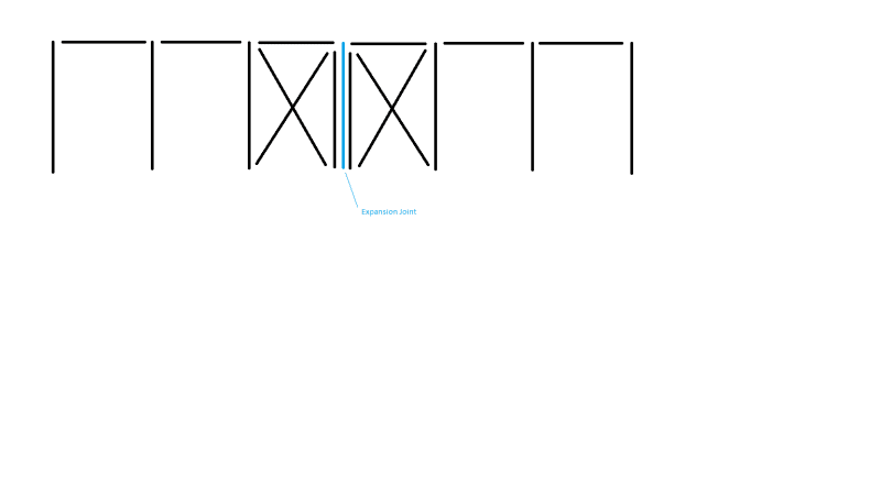
Not a design problem I've faced personally, but its seems to me that you'd break the diaphragm chord at the expansion joint and provide lateral force resisting elements on either side.

expansion_joint_iaxec8.png
 
When I make an expansion joint I actually separate the building into two separate structures. I am in the process now on another building (690' in length) and I have two rows of columns and 2 braces located at the joint. I have heard of having roof members with slip connections but never attempted it...... if I did, I would still end up with a brace along this line to avoid the situation you are ending up with.
 
SteelPE - Thats what I think is appropriate/prudent/best strategy...but braces down that line are not expected and will not be received well.

I see SDI DDM has an example that appears it takes the chord force (that would exist) back into the wall line below...example could benefit from some additional discussion...looking for another example/reference/guidance or confirmation from others on this approach

 
Well, Then you can put a moment frame along that line......... but I wouldn't want to be the one who has to design it.
 
You can also put the braces a line or two away from the joint, and cantilever the diaphragm beyond the last frame and over to the joint. Should be fairly easy to make work, depending on your building's aspect ratio.
 
The purpose of an expansion joint is to allow the two buildings to expand and contract differently, often due to thermal concerns.
There's no way to create this joint that allows the adjacent beams to expand and contract due to temperature changes but to not expand and contract under chord forces.
Sorry that the braces won't be well received, the other option is a moment frame with all the increased steel sizes, costs, and flexibility associated with that option.
 
I agree with wanting to put braces or moment frame on e.j. line as that would create two simple span diaphragms with opportunity for chords but what about the example in the SDI DDM they appear to try to justify it without braces..
 
Full joint.
Design end walls to take all the transverse base shear for strength.
Wind Drift along your joint line will be toughest part. Use fixed bases and grade beams to get more stiffness out of the same steel tonnage. Not saying its easy, but best way to avoid braces and get it to work.
You could also try knee braces off the slab to keep some of the flexibility.
Can also consider using the two gridlines closest or joint as moment/kneebrace frames.
Definitely a challenge, Good luck
 
I think jittles suggestions worth consider.

.... and cantilever the diaphragm beyond the last frame and over [link] to the joint.
 
engjg - are we still on topic with your question? It seemed to me from your original post that you were good to to go on everything parallel to the expansion joint (using the SDI example for transferring shear across the joint), but needed help with the diaphragm chord that is perpendicular to the joint - right? Or did I screw that up?

The chord can't cross the expansion joint, but the diaphragm can (in one direction) with careful detailing. You'll have to break your deck and transfer the shear through some sort of a connection that is rigid in the direction of shear transfer but slips in the direction of the EJ.
 
To clarify moment frame or braces are not wanted on the E.J. or any line. All shear needs to be taken to end walls.

I think I get the SDI example. The E.J. can get be detailed for shear transfer perpendicular to joint but shear is essentially 0 at mid span so not sure what is achieved there... Seems like this essentially becomes (2) three sided boxes (with one open side). A three sided box with a flexible diaphragm? hmmm....isn't their a general thou shalt not against that somewhere? The windward and leeward walls then take the shear (previous chord force) somewhat like a cantilever analogy...I guess I get it but how about drift? how would you quantify?
 
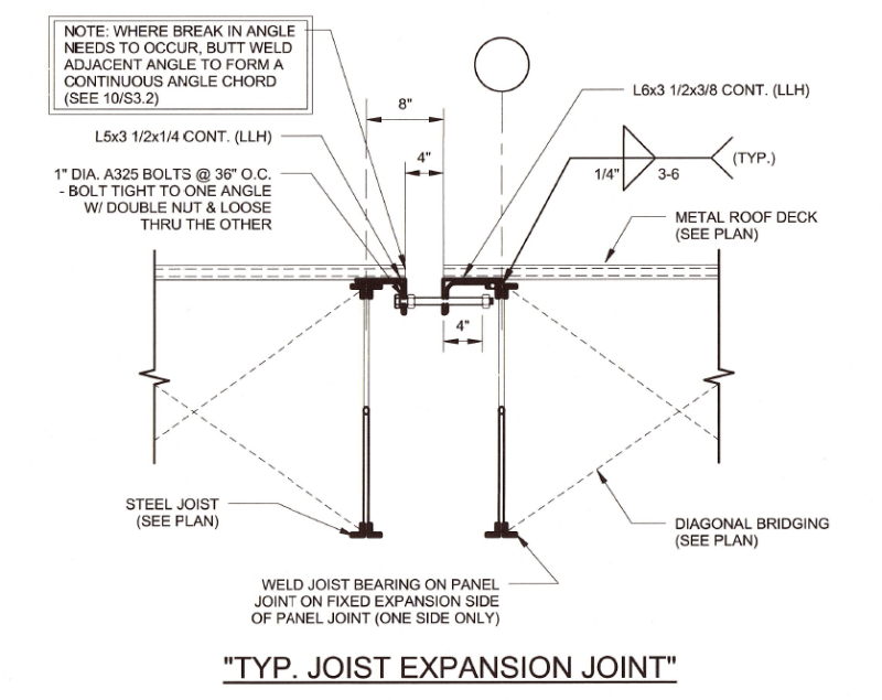
Can you not design the expansion joint to only allow slip in the direction perpendicular to the joint, thus creating continuity for diaphragm forces normal to the sidewall of the building? Then you just need to ensure you provide a load path for chord forces (arising from wind normal to sidewall) down to the foundation on each side of the expansion joint at each sidewall.

The joint can then slip perpendicular to the sidewall and all your chord forces are accounted for. All bracing remains along the perimeter. In this case it doesn't matter if your LFRS is shear walls or x-bracing or moment frames.

I am thinking something similar to this detail:

Capture_vq7vhm.png
 
engjg,

Building separated by expansion joint without linking mechanism will be teared apart eventually.
 
Alternatively, introduce a double column line at the expansion joint and design stiff moment frames for each side. You just need to ensure that the diaphragm is more flexible than the frame lines.

This way for design you have two separate 4 sided boxes.
 
Status
Not open for further replies.

Part and Inventory Search

Sponsor