Eng-Tips is the largest engineering community on the Internet

Intelligent Work Forums for Engineering Professionals

Waste Water Gravity Flow Line Sizing 1

Status
Not open for further replies.

Pavan Kumar

Chemical
Aug 27, 2019
327
0
0
CA
Hi All,

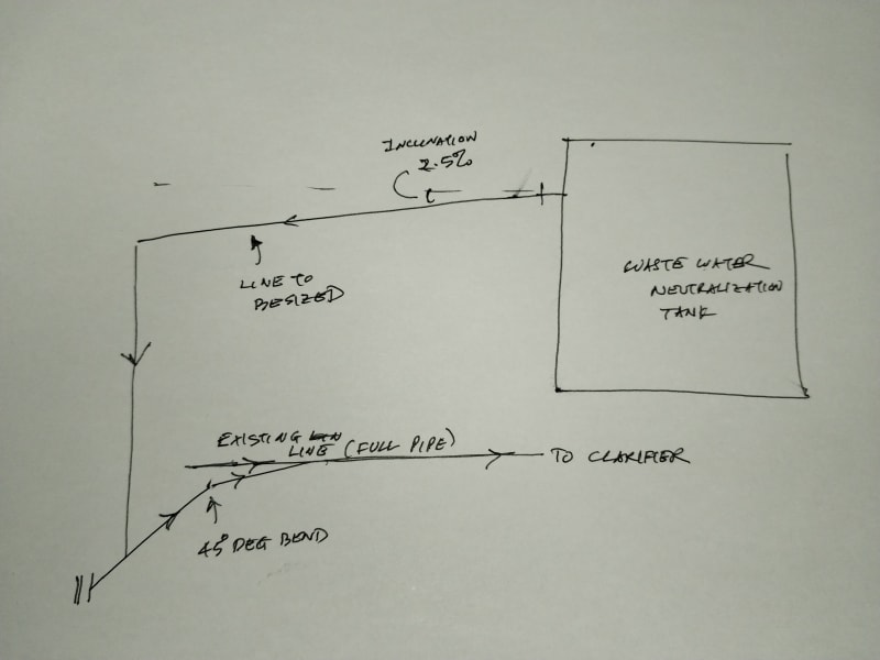
I am tasked to size the overflow line from tank. The line, that is supposed to be sized, comes out from the side outlet has a near horizontal run of 14 ft before it turns 90 degree down and travels 15 ft down and then turns horizontal ( 12 ft run) and connects to main header which is always liquid full. Process data is as below.

IMG_20240725_190517_xyjfgt.jpg


Flow Rate = 3300 gpm
Fluid = water
Temp = 20 Deg C
Density = 62.3160 lb/ft3
Viscosity = 1 cP
Incline = 2.5 %
Pipe fill = 1/2 full
Pipe roughness = 0.0018 inches

I am trying to use the eqn (5) in PD Hills Paper to calculate velocity

VL = (32g*m*i)^(1/2) * Log{ [(e/(14.8m)] + [0.22 u/ (m(g*m*i)^1/2)]}

where
g= gravitational constant in consistent units.
m = hydraulic mean depth = Flow Area / wetted perimeter
i = inclination
e = pipe roughness
u = kinematic viscosity, in consistent units.

I set-up an excel calculation sheet, however I am getting velocity as negative. I am trying to find out what is going wrong and need help here. Also I want to test this formula using the curve given in Fig 3 of PD Hills paper. My reason for using this equation, as opposed to using the curves, is to try different slopes and different liquid depths in the pipe.

Any help will be great help to me.

Thanks and Regards,
Pavan Kumar


Replies continue below

Recommended for you

George - I see that Perry states "The amount of gas entrained is a function of pipe diameter, pipe length, and liquid flow rate..." so I presume L in Fig 6-30 is the length of the pipe. These curves flatten out at high L/D ratios and that would make sense. However, I think it would be better not to design for a flooded outlet as that would work for a relatively narrow range of flows.

Pavan

Pavan Kumar said:
I don't think there is any issue process wise to entrain the air all the way to the clarifier, but I will check with the client. If there is no problem entraining air will air that is trapped in the water not create increased pressure drop in the existing 14" line that is nearly 120 ft long?.

Yes it will and that is the reason for the cyclical behavior that I described in my earlier post (2nd paragraph of post #14 in this thread).


Pavan Kumar said:
Please explain how you got the 6" vent size and the vent line going 10 ft up.

I'm embarrassed to admit these are purely gut feel numbers. You could probable get away with less but I have seen vents continuously spraying droplets and I prefer to err on the safe side. It's hard to estimate the amount of air that has to be vented and it is variable anyway.


Perhaps we are not extracting all the information that is available from the previous operation of this plant. It seems that with a 12" overflow nozzle and a 12" line down to T-2 the old arrangement worked well and did not cause overflowing of T-1. The 24" disentrainment section that I have proposed is in essence a smaller version of T-2. The head required to drive the overflow water into the T-1 overflow nozzle and through the 12" pipe can be supplied by either allowing the level in T-1 to increase, or by taking advantage of the syphon head generated if the vertical downflow leg into T-2 runs full.

It may be possible to install the 24" disentrainment section with piping as similar as possible to what was used between T-1 and T-2, and which you know actually worked. Are you aware of any overflow problems or cyclical behavior in the old arrangement?

Katmar Software - AioFlo Pipe Hydraulics

"An undefined problem has an infinite number of solutions"
 
Hi katmar,

katmar said:
To get the vent to work with a flow of 3300 gpm the ID of the vertical leg must be at least 24". My recommendation would be to install a new 16" nozzle in T-430 and run a 16" line to a 24" ID vertical leg. This leg should extend upwards to about 2 ft above the top of T-430. The top should be closed with a 6" vent going up about 10 ft, and preferably discharging above T-430 in case there are some droplets carried over (See LittleInch's suggestion above). The bottom of the vertical leg can be connected to the existing 14" line using more 14" pipe. You would probably still get some cycling of the level in the tank but it will be only a few inches.

If your client wants to do this as cheaply as possible and is aware of the risks then try the design you sketched earlier. If it does not work then you can install the larger pipe and vent system.

Per your recommendation above, the 16" line needs to be sloped with 2.5% slope or it is the same without slope also. There is practical difficulty of sloping the line with a straight flange on the tank T-430. The client does not prefer it either.

Thanks and Regards,
Pavan Kumar


Hi Everyone,

I Thank you all for the great support I received. I completed my calculations and wrote the Report and submitted to the client to choose from the available options. I have a meeting with them today, I will update you on what option they choose. The options for the Overflow line I proposed are:

1. Flooded Pipe Design: 12" overflow line with a vent at the vertical drop. The horizontal pipe run will have drop in elevation to provide the static head for this part of the pipe. The vertical run already has 19 feet of head available to push the liquid through. This option will have experience cyclic behavior as it is not completely eliminated also there could be overflow frequency same as the current value. I gave this option as the client was not still ready to modify the 12" tank nozzle and install a larger line.

2. Unflooded Self-Venting Piping Design: Suggested 24" nozzle and 24" horizontal run with 1:40 slope. The vertical run shall also be 24". This option does not need a separate vent.


Thanks and Regards,
Pavan Kumar
 
Thanks for getting back to us.

One thing to note for their benefit is that there really isn't an in-between option which works any better and probably worse as you end up with vents, or slugging and surging as the water level rises and air carry over into the d/s equipment.

Remember - More details = better answers
Also: If you get a response it's polite to respond to it.
 
In your first option with the 12" nozzle and sloped horizontal pipe, will the vertical section also be 12"? If so, note that the vent will not remove entrained air. All that the vent will achieve is to control the pressure at this point to atmospheric. As you have said, this means that the horizontal section from the overflow nozzle to the junction with the vertical section must be sloped to provide the necessary static head. My calculation is that this pipe needs to drop at least 3.5 ft, and this drop must be provided by a constant slope in the pipe with the slope starting as close as possible to the nozzle.

This arrangement is still likely to experience cyclical behavior caused by the two-phase flow increasing the friction pressure drop. If this results in overflowing of the tank you can install the vented 24" ID vertical section to remove the air.

I echo LittleInch's thanks for the feedback and look forward to hearing how it works once installed.

Katmar Software - AioFlo Pipe Hydraulics

"An undefined problem has an infinite number of solutions"
 
What's wrong with not having a 24inch overflow nozzle in option 2? So the line from this tank pulls in a lot of air at 12inch - its going to a liquids clarifier, so it burps out entrained air on entry into clarifier. Does that mess up the solids settling operation in the clarifier ? Is there some liquid spreader bar to maintain low velocity and keep low uniform upward liquid flux rate for this entry into the clarifier ?
Am assuming the waste neutralization tank has a good sized atmospheric vent to make up for this air loss by entrainment into this overflow line.
 
Hi katmar,


katmar said:
In your first option with the 12" nozzle and sloped horizontal pipe, will the vertical section also be 12"? If so, note that the vent will not remove entrained air. All that the vent will achieve is to control the pressure at this point to atmospheric. As you have said, this means that the horizontal section from the overflow nozzle to the junction with the vertical section must be sloped to provide the necessary static head. My calculation is that this pipe needs to drop at least 3.5 ft, and this drop must be provided by a constant slope in the pipe with the slope starting as close as possible to the nozzle.


This arrangement is still likely to experience cyclical behavior caused by the two-phase flow increasing the friction pressure drop. If this results in overflowing of the tank you can install the vented 24" ID vertical section to remove the air.

Yes in the first option with 12" nozzle the horizontal and vertical runs both will be 12" with 3.5 ft elevation using two 90 Deg LR elbows as shown below). We could not use a constant slope as it has interfering with the walk-way. Do you see any problems with this kind of elevation drop? Having said that having a vent at the intersection of the horizontal and vertical runs will not offer any help in removing some entrained air as Littleinch mentioned on post #15 at 30 Jul 24 09:25?. I understand to disengage the air from the liquid NFr needs to be =>0.3 and a 24" ID section is needed. So if the air ( hopefully some air) is entrained and goes all the way to the clarifier it will cause two-phase flow and finally burp out of the clarifier riser pipe. For this purpose we are proposing to add an air release vent just before the clarifier and route the vent pipe to the top of the clarifier. As you said it will cause cyclical behavior and may even cause the tank to overflow. I made the Client aware of this possibility. As opposed to the option of having a 12" overflow pipe with no vent and slope before it turns vertical, will the 12" the horizontal with 3.5 ft elevation some benefit some air to be vented. If not then the vent option is no good.

[URL unfurl="true"]https://res.cloudinary.com/engineering-com/image/upload/v1723222179/tips/Sketch_llujsc.pdf[/url]

Hi georgeverghese,

georgeverghese said:
What's wrong with not having a 24inch overflow nozzle in option 2?
Are you referring to Option 1 then?. Please clarify.


georgeverghese said:
So the line from this tank pulls in a lot of air at 12inch - its going to a liquids clarifier, so it burps out entrained air on entry into clarifier. Does that mess up the solids settling operation in the clarifier ? Is there some liquid spreader bar to maintain low velocity and keep low uniform upward liquid flux rate for this entry into the clarifier ? Am assuming the waste neutralization tank has a good sized atmospheric vent to make up for this air loss by entrainment into this overflow line.

We are proposing to add an air release vent just before the clarifier to prevent this air from entering the clarifier. Air burping through the clarifier might interfere with solid settling. What is a liquid spreader bar. I need to understand how a clarifier works. The waste neutralization tank has an atmospheric vent on it.

Thanks and Regards,
Pavan Kumar
 
The reason why I would prefer a constantly sloped pipe is that it will be easier to fill than a vertical pipe and it is only once the pipe is full that it starts generating a static head. But the advantage of the sloped pipe over what your sketch shows will be small and if you use a 12" overflow nozzle whichever solution you go with you are going to get cyclical behaviour. So it probably doesn't matter too much.

When I have seen vents fitted to undersized vertical risers with downflow the air has flowed into the vent rather than out of it. Is the cost of the air release valve near the clarifier less than installing a 24" ID riser? I know that I sound like a broken record, but it really would be much better to reliably remove the air as close to the start of the line as possible.

You did not ever answer my question whether T-430 overflowed when the piping fed directly into T-450. If it overflowed under those circumstances it will only be worse with the new piping.

Katmar Software - AioFlo Pipe Hydraulics

"An undefined problem has an infinite number of solutions"
 
Hi katmar,

I have not checked the cost of the air vent valve and compared it with the cost of 19 ft long 24" ID CPVC Sch 80 vertical riser pipe. I fully agree with your suggestion to use 24" ID vertical riser pipe but the client is really stingy on spending more money. I guess they will know it if or when the operation fails again.

Yes T-430 has overflown occasionally in the past. However it is T-450 that frequently overflows as per the client.


Thanks and Regards,
Pavan Kumar
 
In option 2 : Air gets pulled in through tank vent if overflow nozzle is < 24inch. That proposed vent on this piping isnt going to completely degas this stream, unless it is at a piping high point running at low velocity. Check if there is some entrance chamber in the clarifier for this feed where liquid gets degassed before it goes into the main settling body of the clarifier.
 
Hi georgeverghese,

For Option 2 my proposal was to replace the existing 12" nozzle with 24" nozzle and then have 24" horizontal ad vertical runs with 1:40 slope for the horizontal run.

The client has selected Option 1 and is aware of the risk of tank overflowing, plus they are not interested in replacing the existing 12" nozzle with 24". I am just closing my report with notes that the possibility of tank overflowing is not ruled out and that the client is aware of this.

Thanks and Regards,
Pavan Kumar
 
That was what I suspected the Plant Owner would do.
BTW, dont know how you've derived this possibility of tank overflow in Option 1 when max normal liquid elevation level is at the clarifier is not known to compute available static head. All is see so far is a vertical drop of 14ft and then a vertical rise of 8ft on the piping from your sketch.
 
georgeverghese - you are correct that there is not enough information to definitively conclude that the tank will overflow. But I have seen overflowing in similar setups before and Pavan has confirmed that it did previously overflow when discharging into the second tank. There are two mechanisms that could cause overflowing.

1. If air is drawn into the piping the pressure drop in the long horizontal section to the clarifier will be increased by the two phase flow. This extra head can only be provided by increasing the level in the initial tank, leading to the possibility of overflowing. This could be avoided by installing the 24" ID vertical section with an air vent.

2. If a vent is fitted at the top of the 12" NB vertical section the suction that might have resulted from the formation of a syphon is not available to draw the liquid out of the outlet nozzle. The head required to get the liquid from the tank to the top of the vertical section is made up of three parts. These are the friction in the pipe, the entrance loss in getting into the pipe, and the acceleration loss (Bernoulli) in getting the static liquid in the tank up to the flowing velocity. This head can only be supplied by increasing the level in the tank. The way to overcome this is to increase the diameter of the outlet nozzle and piping and lower all three of these pressure drops.

Katmar Software - AioFlo Pipe Hydraulics

"An undefined problem has an infinite number of solutions"
 
Am not familiar with flow equations used in the waste water industry, and neither am I clear about interpretation of the Kalinske overflow graph Fig 6-30 in Perry. Not having basic info on clarifier level doesnt help either.
Moving out to 24inch may be the solution(?), but there is ambiguity at the moment for me that a 12inch overflow line wont do. And if it wont, at what flow will it suffice - not known either. That existing long low point section leading up to the clarifier doesnt seem right either.
I'll leave it at that given these ambiguities / unknowns.
 
Status
Not open for further replies.
Back
Top