Continue to Site

Eng-Tips is the largest engineering community on the Internet

Intelligent Work Forums for Engineering Professionals

  • Congratulations KootK on being selected by the Eng-Tips community for having the most helpful posts in the forums last week. Way to Go!

Wastewater Wetwell bellmouth annular velocity

Status
Not open for further replies.

Nutzman

Mechanical
Nov 2, 2020
57
Hi all,

I have a number of sites where the pipework was sized to cater for a flow on the day. Thanks to growing populations, the station needs to be upgraded.
It's easy to increase pump and pipe sizes "in-station" to cater for the increased flows. However what is often ignored is the pipework through the wetwell/drywell wall. and by association the bellmouth in the wetwell.
There are industry standards stating the clearance between the underside of the bell mouth and the wetwell floor. Typically D/2 to D/4.
Invariably what happens is the "100mm" pipe through the wall had a bell mouth with a clearance of (Bellmouth OD - 185mm/2 = 92.5mm underside clearance).
The station is upgraded to a 150mm (pipe through the wall) in station. So the bellmouth should have a clearance of (Bellmouth OD of 245mm/2 = 122.5mm).
But the pipe through the wall and bell mouth were not upgraded, so we have a 100mm pipe/bellmouth with a 150mm velocity.
The question is, does anyone have the formula for the calculate the annular velocity entering the bellmouth.

Thanking you all in anticipation.

Nutzman
 
Replies continue below

Recommended for you

Nothings easy in this world....

Remember - More details = better answers
Also: If you get a response it's polite to respond to it.
 
Especially not when you knee deep.....[flush]
 
Hi all,
Many thanks for your collective input. Having perused all the information, it has become a little more confusing.
Based on the above, the thinking has been to calculate the velocity at the "cylinder periphery" of the bell mouth.
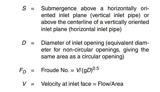
However in the Hydraulic institute document mentioned above they mention the velocity at inlet face.

Submergence_formula_id8spu.jpg
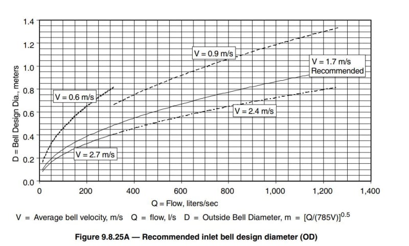
Recommeded_inlet_velocity_ktwjxe.jpg
[URL unfurl="true"]https://res.cloudinary.com/engineering-com/image/upload/v1711365799/tips/Bellmouth_sketch_aeuvbz.pdf[/url]

They further suggest an "recommended" inlet velocity of 1.7 m/s. If that is 1.7 m/s at the face, as per the hatched section in the hand sketch, what is the velocity going to be in the "straight section of the pipe?

If I apply the area formula of a 185mm dia bellmouth the area is 0.0268 m^2.
If I apply the area formula to the cylinder dia/height, the area is 0.0537 m^2.

Both would produce a vastly different velocity.

Confusion reigns.

Your collective assistance would be appreciated.
 
Bellmouths are definitely a bit odd and no bellmouth is the same so without a diagram I think you're lost.

The flow transitions from laminar to turbulent as the diameter reduces and takes a little while to become fully turbulent.

"Outside Bell diameter" / "Bell design diamter" is very vague and if your bellmouth essentially ends up with a horizontal edge then where is this diameter?
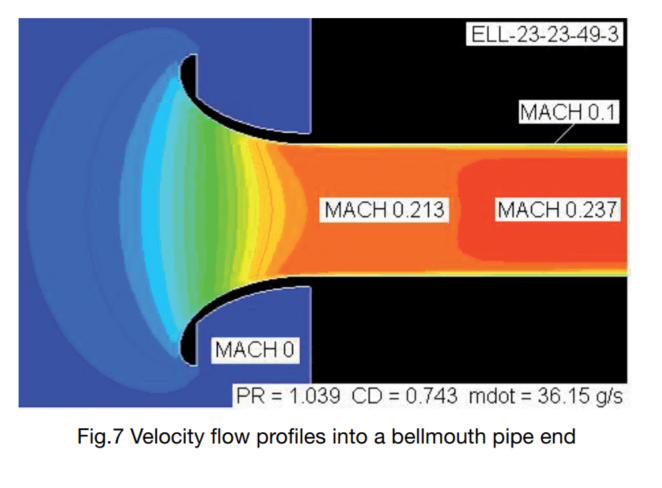
If you look at the attached figure 7 (I know it's air, but the same will apply for water), you can see the constant inlet velocity is a parabola. This though doesn't account for the fact that you have a wall / floor in place which buggers things up even more

Screenshot_2024-03-25_125816_vzgzsu.png


Remember - More details = better answers
Also: If you get a response it's polite to respond to it.
 
Littleinch,

Very well expressed. And as you state the diagram is for air, but the same principle applies to liquid.
To add to my problem, there is a 90 deg bend at the Mach 0.237 mark. So another change of direction and more turbulence. Then a change in diameter (100 to 200mm) and then the flow is presented to the inlet of the pump (on another 90 deg long radius bend). So little hope of "steady flow". Result = pump not achieving expected flow?
 
Plus the small gap between the flat line of your bell mouth end and the floor, walls and that strange looking ramp will mess up the flow pattern. You're probably getting a highly turbulent swirling mess of water going into your pump which it won't like for sure.

But if this is indeed sewage then you can't do much to stop it.

I have seen before it does take 2-3 D of straight pipe at least to get the inlet stream to act in a fully turbulent manner. Could you remove that first elbow and just have a longer length of straight pipe with the inlet being horizontal?

Remind me what you're trying to find / what's the problem here?

Remember - More details = better answers
Also: If you get a response it's polite to respond to it.
 
The small gap between the floor of the sump and the underside of the bellmouth is designed to create high velocity in order to prevent solids from accumulating on the sump floor. You don't want solid buildup and a slump, thereby choking the pump.
That's the reason why one cannot extend the pipe straight through the wall. (and eliminate the bend).
The original question, was to determine the velocity into the bellmouth based on diameter and clearance from the floor.
 
Fair enough, but creating high velocity in a suction / inlet situation will create losses. And make it very difficult to determine your velocity profile.

You're going to need something like CFD to figure this one out.

Could you not take a small slipstream off the pumped outlet and feed it back into the base of the sump to swirl things up a bit?

However , given your bellmouth on your drawing is more like a straight edge reducer, I suspect your D is simply the OD of the bell mouth outer circle when you look at the data listed. Of course other losses will be present in creating these large velocities to continuously scrub the floor of the pit.

Remember - More details = better answers
Also: If you get a response it's polite to respond to it.
 
Status
Not open for further replies.

Part and Inventory Search

Sponsor