Continue to Site

Eng-Tips is the largest engineering community on the Internet

Intelligent Work Forums for Engineering Professionals

  • Congratulations cowski on being selected by the Eng-Tips community for having the most helpful posts in the forums last week. Way to Go!

Water distribution controls for a small plant 6

Status
Not open for further replies.

amazing azza

Industrial
Apr 26, 2017
130
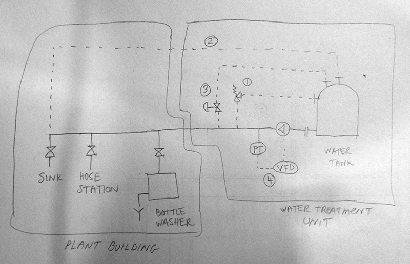
Hello friends, I am planning a water distribution system for a small plant. There are a number of machines that use water (ie. continuously if machine is on), and there are a number of sinks and hose stations which may be opened at any moment for an arbitrary length of time.

What are some of the typical ways to control supplying water to this mix of users? Here is what I can think of:

1. Have the supply pump be on 100% of the time and install an overpressure valve at the pump outlet that sends pump output back into the water tank. This way the pressure in the supply line is always equal to (or less than) the rating of the overpressure valve.

2. Have the supply pump be on 100% of the time and pump water in a loop around the plant that leads back into the water tank. This way the supply line is always pressurized at the pressure that the pump can deliver. (Naturally, this value would be chosen wisely).

3. Have the supply pump be on 100% of the time and have a control valve at pump outlet that sends the output of the pump back into the water tank depending on the pressure in the line. Using PID control, the pressure in the supply line would be kept constant.

4. Install a pressure switch on the pump outlet such that if someone opens a valve (or machine turns on), the pressure in the line will fall and the pump will turn on (maybe with inverter control). Pump would turn off when the pressure in the line spikes as the valve is eventually closed.

I experimented with #4 a bit, but found that in real life the line does not stay pressurized, but rather falls to low values (~0.5 barg) fairly quickly once the pump is turned off.
 
Replies continue below

Recommended for you

Do you have a PFD or P&ID that you could share? That would be great.

"I have not failed. I've just found 10,000 ways that won't work." Thomas Alva Edison (1847-1931)

 
Here is a crude sketch of the different possibilities:

pid_exbpp8.jpg
 
Put a tank on a high roof, or on a tower.
That will provide a nice constant pressure supply for the users.
Then all you have to worry about is refilling the tank when the level falls a bit.


Mike Halloran
Pembroke Pines, FL, USA
 
Yeah.. the tank is already in place, moving it is not an option
 
Hi Azza,
Without a check valve on the pump discharge, there is no way to hold pressure on the line, there therefore your comment " the line does not stay pressurized, but rather falls to low values (~0.5 barg) fairly quickly once the pump is turned off. " Even with a check valve, a small leak will quickly bleed the pressure off. I suppose that you could install a bladder tank. along with a check-valve, to keep the pressure up, and then start-stop the pump on pressure limits.
BTW, how large is this pump (in terms of motor NP hp)? Obviously if the pump is too large then the bladder tank cost could become excessive.
BTW, does the tank have a level transmitter which could turn the pump off on lo-lo level? This might save the pump if the tank becomes empty. I guess there is not flow-transmitter on the pump discharge?
There is no downside to frequent starting / stopping the motor as it is VFD controlled.
GG

"I have not failed. I've just found 10,000 ways that won't work." Thomas Alva Edison (1847-1931)

 
GroovyGuy, hey thanks for looking over my drawing :)

There actually is a check valve (and isolation valve), but I neglected to draw it in a rush. I will post a picture of the setup later. There is also a level sensor on the tank w/ H/L/LL setpoints. As you noted, the LL cuts off the pump. Motor size is 7.5 HP (5.5 kW). There is no flow sensor currently, but that is something that could easily be added as I have reserved space for it.

Ah, so you think using acceleration function of the VFD will allow frequent start/stops? That was one of my concerns. The other is picking the low pressure ON-point...
 
Howdy Azza,
Is the motor inverter-duty rated, most motors theses days are rated as such. If not, you should consider installing a dV/dt filter on the drive output.
I see no reason why you could not start-stop the pump as often as required to suit demand.
I don't see the ON-pressure setting being an issue, but rather I see the OFF-pressure setting being more of an issue. I would suggest that for starters, that ON-pressure limit < 75% of nominal would be OK. The real trick will be to select an OFF-pressure limit. ie Don't forget that the VFD will try to keep the pressure close to the normal setpoint, and the only way to ensure that the system can hit the OFF-pressure limit is to ensure that the VFD minimum speed is high enough to ensure a high pressure can be obtained during low-flow or no-flow conditions. This can be a bit tricky to set up. Having a Flow-transmitter helps a lot ( ie you can simply stop the pump on no-flow ).

"I have not failed. I've just found 10,000 ways that won't work." Thomas Alva Edison (1847-1931)

 
Often a small bladder tank is included on the outlet side of the pump in these cases. It allows the water to start flowing the instant it's called for giving the pump some finite time to spool-up. Systems control to pressure looked at next to the little bladder tank which also provides some pressure signal filtering. I've seen the commercial packages turn down the VFD briefly (almost unnoticeably) every 60 seconds or so to see if the pressure drops meaning a demand is really occurring. Since the VFD is PID'ing to the pressure it can not actually tell when there is no longer flow. That's how it's done avoiding flow sensors.

Keith Cress
kcress -
 
GG, itsmoked, thank you for your valuable advice! Here is a picture of the pumps, as promised. (Should have used a tank outlet isolation valve, but alas. Will add next time I take the piping apart)

pumps_szrq9h.jpg


The bit about stopping the pump ... I must admit I did not think of that. Somehow I assumed that even with PID control there would be some degree of a spike when all outlets are closed, but before the controller corrects. With this new info in mind, I am quite open to the flow sensor. Now, all I gotta do is source them...hahaha.

I looked into the dV/dt filters. They are quite beefy, aren't they? The ones from the maker of my drive (Toshiba) are about the same size as the inverter itself and weigh... get ready... 30 kg (65 lbs)! Does this sound about right? Where would you mount this thing? Not in the cabinet, right? Also, my cables are < 50m (150 ft), is it still justified?

Not sure if my motors are inverter rated, probably not, unless it comes standard somehow. The fan certainly runs slower if the frequency is down. I've attached the nameplate, if there's an easy way to tell.

motor_ymat9j.jpg


About the bladder tank, how big would it have to be for a 15 m3/h (65 gpm) flow?
 
Hi Azza;
See the following link for Gould's bladder tanks;
WRT size I would spec their largest standard size of 115usg.

The dV/dT filter that I had in mind can be found at;
These filters are small (ie 8lbs for an 11A filter in an open type configuration).
I would contact your pump/motor OEM and ask if the motors are VFD rated. I'd be surprised if it wasn't so rated. If the motors are in fact VFD rated, that together with your short motor feeder length (of 50m), I would recommend that a filter is not required. However, if the motors are not rated for VFD duty, I would recommend that the filters be installed.

GG


"I have not failed. I've just found 10,000 ways that won't work." Thomas Alva Edison (1847-1931)
 
Hi Azza; Groovy's got some nice links there and I pretty much agree with his filter suggestions.

I don't know if those motors are VFD rated. One thing that can confuse you is if you ask a maker, "Is this VFD rated?" they will almost always tell you NO you need to pay 2X the normal price for that. Their fall-back argument is always that if there isn't an auxiliary motor running the fan then how could it be VFD rated? In pumps you never need that aux fan since the motor is going to have to spin at least 50% of the rated speed to make a centrifugal pump do anything and when it is running at 50% the load is more than covered by the existing shaft mounted fan.

As for the tank as a comparison a residential little pressure tank is usually on the order of a gallon and it has to contend with faucets banged on and off. If your plant can have a pressure dip without a problem you could go pretty small. If the run is long and big then you'd want a bigger tank that can help buffer that big inertial bang if the bottler bangs off not having a soft valve. In that case I'd probably go bigger too though you might not need 150 gallons.

A problem with a flow sensor is that if it has to see a large flow it may be lousy at seeing a small flow like a hand washing dribble, whereas that would cause a significant pressure change.

Keith Cress
kcress -
 
GG, itsmoked, did some pump control trials today. The results are exactly as you described. Quite easy to set the low ON pressure. But it is the high STOP pressure that is more of a problem. Under PID control, the frequency just kept getting turned down after all outlets were closed. Eventually it got down to 0.8 Hz and stayed there steady. Tried not using PID at all, and just blasting the motor 100% with only the low/hi alarms being active. This sort-of worked. For any one valve I could pick good start/stop points where the alarms could reliably start/stop pumps as valve was opened and closed. However this approach did not scale to even two valves. Or opening 1/2 or 1/4 of the way. What would have worked for one, did not work for another. With partial opening pressure spikes were a nuisance and led to cycling.

Looks like I need a flow sensor. Any preference between "paddle" and "thermal flow" types?

I will try to find out about the VFD rating of the motors, except these vendors are not very knowledgeable (sigh). The bladder tank sounds like a solid idea. Wish I had thought of it earlier. I guess it will be the next option to explore after trying with the flow sensor.
 
Thanks for the feedback. Nice looking system BTW. Clean piping.

I believe your VFD should have a do-not-run-below-this-speed parameter setting where you can have it quit at ~10 or 20Hz.

I also believe what you need is not a flow sensor but a controller that does... essentially what I described above looking at just the pressure. A very small PLC or something similar. Even an Arduino would do it.

I suspect the thermal type might be more applicable to your (future failed) attempt at trying to control this with flow.

BTW Using a flow sensor, how exactly do you get any measured flow to actually start the pumps in the first place?
URL]


Keith Cress
kcress -
 
itsmoked, yes, forgot to mention in the update:

Tried setting the minimum frequency. The "steady state" under the testing conditions was 47.5 Hz. Tried setting the low frequency limit on the inverter up to 40 Hz without being able to cause pressure to rise when all valves were closed. Maybe this effect could be achieved by going higher, but I don't see it as a viable solution. The actuation range would be severely limited, and you might as well just run the pump at full power (which did not work out). Oh, and control is much less stable with this limit in place.

Here is my plan with the flow sensor. The low pressure would be sensed by the pressure sensor with some hysteresis. This low pressure alarm will act as a start button being held. While the rising pressure clears the hysteresis, the flow is expected to pick up enough to trigger the flow sensor, which will act as a stop button being held unpressed by the flow. Thus, pressure to start, flow to stop. Does this make any sense?
 
Howdy Azza,
The only issue that I see with using a low-flow condition to stop the pump is finding a flow-transmitter that is accurate at low-flow conditions to be sufficiently reliable. First, you must decide at what low-flow condition you will stop the pump (ie 1.0 usg / minute)
Options include, in no particular order;
- vortex type
- paddle-wheel type
- ultrasonic type
- magnetic (mag-flow) type
- thermal type
- other??
Perhaps someone with more experience with FTs could offer a solution.
You should not discount itsmoked's suggestion, ie;
I've seen the commercial packages turn down the VFD briefly (almost unnoticeably) every 60 seconds or so to see if the pressure drops meaning a demand is really occurring. Since the VFD is PID'ing to the pressure it can not actually tell when there is no longer flow. That's how it's done avoiding flow sensors.
The above suggestion is actually pretty slick, and you don't need any additional hardware. Of course you will need a PLC to implement the required logic, but I assume that you have one of these about somewhere, correct?
GG

"I have not failed. I've just found 10,000 ways that won't work." Thomas Alva Edison (1847-1931)

 
"Of course you will need a PLC to implement the required logic"

Ah, yes, the one thing I do not have. I made this panel in an old-fashioned style.. ie, all relays. I guess I was trying to keep it simple, haha. (If I did it again, I would certainly use a PLC).

The flow sensor I am currently looking at is a paddle type. Seems it can read fairly low depending on the model. SMC IF3. I believe this to be the easiest option for me right now. It will fit into the schematic with minimal mods.
 
Looks like I will be adding a "smart relay" to the project. With this addition, itsmoked's trick about slowing down the VFD comes to mind. May I ask some additional questions about it?

itsmoked said:
I've seen the commercial packages turn down the VFD briefly (almost unnoticeably) every 60 seconds or so to see if the pressure drops meaning a demand is really occurring.

Is the implementation part of the PLC code, ie, turn off pid, slow down the frequency, if pressure < threshold then ... else ..., or is it more of a physical perturbation to jolt the pid controller out of a local minimum? An example of the latter would be - vfd is driving from external (pid control) signal and we go and override that input and set the frequency to 1 Hz for a fraction of a second, and then return back to external frequency input (and see what the pid controller does in response)?
 
It's a PLC implementation like so:

1) Has a steady state pressure been reached(This could be at zero flow)? No - goto 1; Yes - goto 2
2) Yes - start a 60 second timer. goto 3
3) Time-out? No - goto 4; Yes - goto 5
4) Still steady-state? Yes - goto 3; No - clear timer and goto 1
5) Reduce the speed 30%. goto 6
6) With tank bigness/flowsmallest consideration, is the pressure dropping? Yes - return 30% goto 1; No - goto 7
7) Spool pump down to stopped.
8) Pressure below X? Yes - goto 1; No - goto 8

This scheme requires a check valve or the pressure will never stabilize because as soon as you reduce pump speed the pressure will sag to whatever the tank head is at any particular moment - looking like 'water consumption'. Of course you need a check-valve anyway so you never get process water back-feeding to the source or tank.

Keith Cress
kcress -
 
Status
Not open for further replies.

Part and Inventory Search

Sponsor