Hi. this is a follow up on my previous post. I think it would be better to make a new thread because there is a clear, specific question now.
My project is about supplying water to our fogging system which is basically another pump and also end user flow.
The requirements from the device's manufacturer are 12 m3/hour at 3-4 bar. However real flow at which is the system operating is 4 or 8 m3/hour, depending on whether single string is on or both. Please note, that the flow is always restricted to 4 or 8 m3/hr by the system.
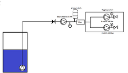
I would like to use 2 pumps in series of which the second pump is supposed to be Ebara either Matrix or 3M. First pump will be submerged in the water tank, supplying Ebara which is supposed to act as a pressure booster. The supply line will be regulated by VFD and pressure control loop. There will be a pressure tank and high flow filter unit in the system.
Please find below our system curve along with the pump characteristics. The dotted lines, barely visible are standalone pumps, the bold lines are pumps in series and system curves.
I created system curves for 3, 3,5 and 4 bar that is a range required for the end user. Also I created the characteristics for 10 and 20% speed reduction.
I can see that the Matrix pump has a much steeper line than 3M. By looking more closely I would say by going for the "steep" pump it will need more precise speed tuning but I can get the output want.
Also important to mention,the steep one is significantly cheaper.
I would be very interested in getting a more detailed view what are the real advantages and disadvantages of both solutions and which one fits our system better.
Due to the lack of practical experiences I cannot predict that, so I would like to ask you for advice. Is it all about the VFD setting and fine tuning in my scenario or do I miss something?


Thank you.
My project is about supplying water to our fogging system which is basically another pump and also end user flow.
The requirements from the device's manufacturer are 12 m3/hour at 3-4 bar. However real flow at which is the system operating is 4 or 8 m3/hour, depending on whether single string is on or both. Please note, that the flow is always restricted to 4 or 8 m3/hr by the system.
I would like to use 2 pumps in series of which the second pump is supposed to be Ebara either Matrix or 3M. First pump will be submerged in the water tank, supplying Ebara which is supposed to act as a pressure booster. The supply line will be regulated by VFD and pressure control loop. There will be a pressure tank and high flow filter unit in the system.
Please find below our system curve along with the pump characteristics. The dotted lines, barely visible are standalone pumps, the bold lines are pumps in series and system curves.
I created system curves for 3, 3,5 and 4 bar that is a range required for the end user. Also I created the characteristics for 10 and 20% speed reduction.
I can see that the Matrix pump has a much steeper line than 3M. By looking more closely I would say by going for the "steep" pump it will need more precise speed tuning but I can get the output want.
Also important to mention,the steep one is significantly cheaper.
I would be very interested in getting a more detailed view what are the real advantages and disadvantages of both solutions and which one fits our system better.
Due to the lack of practical experiences I cannot predict that, so I would like to ask you for advice. Is it all about the VFD setting and fine tuning in my scenario or do I miss something?
Thank you.
Last edited: