Continue to Site

Eng-Tips is the largest engineering community on the Internet

Intelligent Work Forums for Engineering Professionals

  • Congratulations cowski on being selected by the Eng-Tips community for having the most helpful posts in the forums last week. Way to Go!

Water tank Manhole Design Example

BR0

Structural
Nov 10, 2010
51
Hi All,

I was wondering if anyone knows of a suitable textbook or other industry source with examples of water tank designs for some of the ancillary items. Currently, I'm trying to find examples of manhole and vent sizing design in new or existing water tanks.

I have pretty good examples of the overall tank design, IE, shell and roof design.

I also have API 650 and section 5.7.5, which have minimums, but it notes to provide "calculations ...for the maximum required thickness". I was hoping to get worked out examples if they exist.

Thanks
 
Replies continue below

Recommended for you

but it notes to provide "calculations ...for the maximum required thickness". I was hoping to get worked out examples if they exist.
I have copy and pasted the same clause .

The minimum cross-sectional area of the required reinforcement shall not be less than the product of the vertical diameter of the hole cut in the shell and the nominal plate thickness, but when calculations are made for the maximum required thickness considering all design and hydrostatic test load conditions, the required thickness may be used in lieu of the nominal plate thickness. The cross-sectional area of the reinforcement shall be measured
vertically, coincident with the diameter of the opening.
As stated by the clause , there are two methods;

- If you do not want to make calculations , provide the area of nominal shell plate thickness times the diameter of the opening when viewed through the vertical plane, that is , the required area of reinforcement = D* tnom. ( D is dia. of the hole and tnom is the thk. of the subject shell course at the opening )

- If you want to make calculations , the required area of reinforcement = D* tr. ( D is dia. of the hole and tr is the required shell thk. at the opening )
In this case, the extra material in the shell beyond the required thickness is considered to make some economy .

I will check my old documents for a sample calculation and post if i can find. Or better , you may provide some details regarding the tank to get better responds.
 
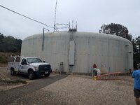
Hturkak, Thanks for the response. I'm evaluating an 80-foot diameter x 15-foot tall welded steel water tank. The shell plate is 1/4" thick. Our primary scope was a roof, wind/seismic, and foundation analysis and evaluation. We do this scope a lot, including the construction documents for repairs. However, in our area, the design for new tanks is done as a delegated design, and the manufacturer does all of the detail designs, including for items like manholes and vents.

However the client requested us to look at the manholes and make recommendations as they felt they weren't adequate.

The current size of the two shell manholes is 2 feet in diameter. The more recent AWWA D100 requires one of them to be 2.5 feet in diameter.

For my report, I don't have to do the actual design and detailing at this point. However, I do want to check to see if there will be any issues with making this recommendation. I also want to determine how complex the design and detailing are. I want to determine if we need a sub-consultant for the construction documents that will be in the next phase.

Even if we had the contractor provide a delegated design, we do like to detail an acceptable design so that the bidders are all pricing the same thing.

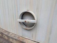
Thanks, BobPXL_20240926_160701465.jpgPXL_20240926_160924185.jpg
 
Ah, the inswing-manway. That is not covered by API-650.

Per AWWA D100, the excess shell plate area and the area in the neck are included in the reinforcing. That style of manway has the neck intentionally built up to furnish full reinforcing area via the neck, without needing a reinforcing pad. Note that neck area included is 4 x neck thickness both inside and out.

If you want to increase the manway size, the easiest way will be to just put a new flanged manway at some different location around the tank and retain the existing manways where they are. New manway style need not match that style.
 
JStephen, That sounds like a good suggestion to put another one in a separate location. I think they do want an in-swing manhole, though.

Do you know any document that provides a design example and also typical detailing. Maybe one of PIP documents?

That style of manway has the neck intentionally built up to furnish full reinforcing area via the neck, without needing a reinforcing pad. Note that neck area included is 4 x neck thickness both inside and out.
Even defining the different terms that are used in AWWA D100 would be beneficial, such as neck area, etc.
 

Part and Inventory Search

Sponsor