Anandhanachu
Mechanical
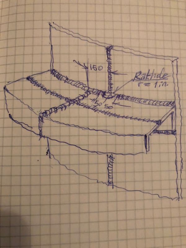
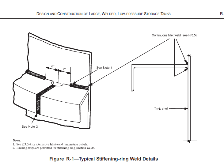
We want to use the below shown type of stiffener ring in staorage tank.
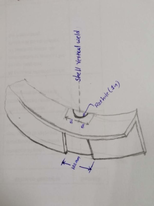
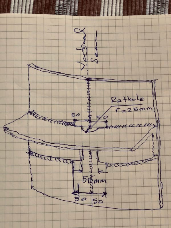
How could I provide rat hole in this stiffener.
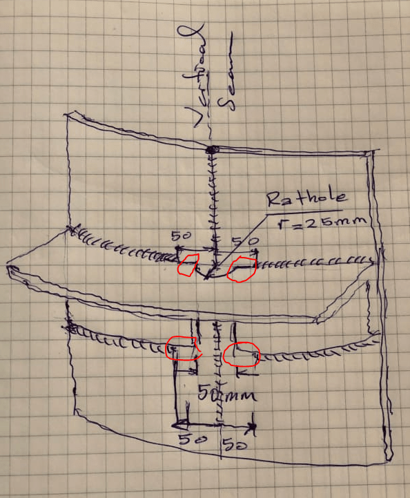
If so what happens at the intersection of stiffener and shell vertical joint?
How could I provide rat hole in this stiffener.
If so what happens at the intersection of stiffener and shell vertical joint?