Continue to Site

Eng-Tips is the largest engineering community on the Internet

Intelligent Work Forums for Engineering Professionals

  • Congratulations KootK on being selected by the Eng-Tips community for having the most helpful posts in the forums last week. Way to Go!

Weak axis bracing on drag strut/collector steel beams?

Status
Not open for further replies.

MJC6125

Structural
Apr 9, 2017
119
Can you rely on a slab-on-metal deck or a roof deck to prevent weak axis bucking of a steel beam? Specifically when you have a WF beam in line with a brace and the beam is acting as a drag strut, whether its at the roof or a floor level. Let's assume framing is running parallel to this beam, so you don't have any members framing into it. This beam will need to carry an axial compression load under certain lateral loading conditions.

I'm pretty sure you can't rely on the deck for weak axis buckling of a WF beam, but I'm not positive on that. Wood stud walls are sometimes built with sheathing only on the outside (i.e. in an unfinished garage), and I think those studs typically need to rely on that one sided sheathing for weak axis bracing. So are there certain scenarios where decking/sheathing can be relied upon for weak axis buckling and certain scenarios where it can not?

For the original stated example, assuming the deck doesn't provide weak axis bracing, do you typically find that these collector steel beams work without needing weak axis bracing or that you install supplementary bracing to prevent weak axis buckling?
 
Replies continue below

Recommended for you

Maybe it is just regional differences in terminology but I'm a bit lost with this question. I think a diagram would help. Everything you describe sound like the decks very would be points of pinned restraint and so you can calculated the columns effectively length from that.
 
It sounds like your question is does bracing one flange of a WF section cause sufficient restraint to consider it fully braced in in axial compression?

I am curious to hear the responses. My suspicion is no for most cases unless the beam has a pretty favorable aspect ratio.
 
Agree with XR250, the deck braces the flange is is connected to, but not the other flange. To be conservative, I would assume the beam is unbraced, and check it for the axial load plus bending. If the drag strut force is small, perhaps you can rationalize that it stays within the braced flange. But then, how does it get through the beam end connections?

DaveAtkins
 
We do not rely on the deck as continuous bracing for a beam/drag strut experiencing compression loads, and will treat the length of the beam as the unbraced compression length.
If the beam doesn't pass in combined bending/compression, we`ll upsize the beam a little bit. If that doesn't work, we`ll add angle kickers from the bottom flange of the drag strut to the top of the adjacent beam and consider that to be a brace point. In this case, the bottom flange is braced by the kicker and the top flange is braced by the deck.
 

What are the certain lateral loading conditions ? Please specify to get specific responds..


The restraint provided by decking to the beams fully depends on orientation and fixing of the deck to the beams. The decking spanning perpendicular to the beam cam provide restraint if adequately connected (in this case,with welded shear connectors).

Regarding the beams running parallel to the ribs, the restraint provided by decking is negligible so , should be nelected for the design putpose.

 
Yes, my question is: does bracing one flange of a WF section cause sufficient restraint to consider it fully braced in axial compression?

Certain loading conditions means if the lateral load is going in one direction on the building, let's say from north-to-south, the drag strut will be in axial compression. If the lateral load was going the other direction, let's say from south-to-north, the drag strut would be in axial tension and we wouldn't have a axial bracing issue. The main question I have is the one that XR250 more succinctly described.

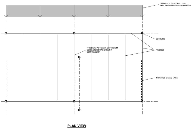
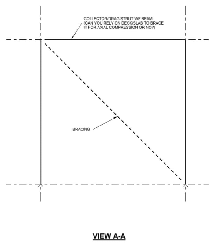
Diagram of situation:
Capture_yccqqq.jpg

Capture_2_kxtwgl.jpg
 
AISC 341 (Seismic design manual) section 8.3 discusses this. The deck parallel to the collector/drag strut is usually not considered to brace the top flange. Generally in this configuration you'd have joists framing into the collector which would provide weak axis and torsional restraint. Deck parallel to the collector is considered to brace the top flange and not the bottom flange. Major axis unbraced length is taken as the full length of the beam.
We typically add kickers even when joists frame into the collector to further reduce the weak axis unbraced length.
If these are composite beams, you can simply take the stress ratio from the composite beam analysis and resolve it into DL, LL, SL, etc bending stress components (depending on your analysis software). Then take your axial/column stress ratio and combine the two using your seismic load combinations (including overstrength in the axial calc).
 
In your picture above: I would not consider those collectors to be fully braced. Top flange would be braced by the deck running perpendicular. I'd recommend adding kickers to the bottom flange at 6ft o.c. or so.
 
dold, can you point me to where exactly section 8.3 of AISC 341 discusses this issue? I have AISC 341-16, which has the sections broken up into letters instead of numbers. I also have AISC 341-05, but section 8.3 is about columns.
 
Sorry, I always just call the Seismic design manual "341" but I guess technically those are the provisions (part 9).
Just before the provisions is Part 8 "Diaphragms". There is a design example included. Let me know if you still can't find it.
 
MJC6125 said:
Yes, my question is: does bracing one flange of a WF section cause sufficient restraint to consider it fully braced in axial compression?

In general, no. Unless the restraint to the braced flange also braces the section torsionally, your real world condition is approximated as:

1) Strong axis: KL = full length of beam.

2) Weak axis: KL = effectively zero if the deck runs perpendicular to the beam or if there is a suitably connected concrete deck slab.

3) LTB / Torsional: KL = distance between perpendicular framing members or kickers that would, effectively, brace the beam rotationally.

The handling of #3 is the interesting bit. I've seen three approaches predominately:

A) Ignore explicit LTB checking for #3 and, instead, design weak axis buckling at [KL = distance between perpendicular framing providing rotational restraint]. This will generally be conservative as, for that assumed effective length, weak axis buckling will always produce a lower capacity than LTB. This is what I see folks do 95% of the time as it's simple, conservative, software/manual friendly, and doesn't impact beam sizing much. I've seen this approach espoused in past versions of the seismic design manual.

B) Check LTB assuming no bracing between between perpendicular framing providing rotational restraint which falsely, but conservatively, assumes that the beam rotates about a point in space below its shear center under LTB.

C) Check LTB assuming that the the beam rotates about a point in space located at its top flange under LTB. This is often referred to as constrained axis buckling and is computationally complex, yields a lot of extra capacity relative to , and is built into no commercial software package that I know of. Still, a big equation is just an equation and, if you're doing things with custom spreadsheets, it's not all that big of a deal. I usually only do this as a desperation play if I'm trying to get something existing to work or if I'm dealing with with OWSJ as the perpendicular framing and I don't want to get into kickers for some reason. This method has also made an appearance in previous versions of the seismic design manual.
 
Status
Not open for further replies.

Part and Inventory Search

Sponsor