Greetings,
I need some tips on solving a specific problem that keeps bugging my mind. We are working as a detailer in a rather large international project. My problem is with how to strengthen a beam web against bolt bearing?
So in this particular project, there are some beams connected to huge girders with wide flanges. These connected beams, have both very high shear and axial forces. Don’t ask me why, that’s what designer provided. And funnily enough these connection forces are nearing almost the beams respective capacity. Anyway, since we have both high shear and axial forces, we used shear splices to connect them to girders. (see attachment1).
Idea was simple, a plate will protrude from girder web, welded to both flanges of the girder as well as its web. Beam end will be placed against it and web splice plates will connect gusset to beam web from both sides. That way we will not have any in plane bending due to axial force as in the case with simple shear tabs. Also we would benefit from double shear effect. Anyway, problem is we often require web strengthening because of bolt bearing.
I also need to mention that owner refuses to use site welding or having flanges connected since it alters structural behavior. They have their reasons but we argued to find a solution but to no avail.
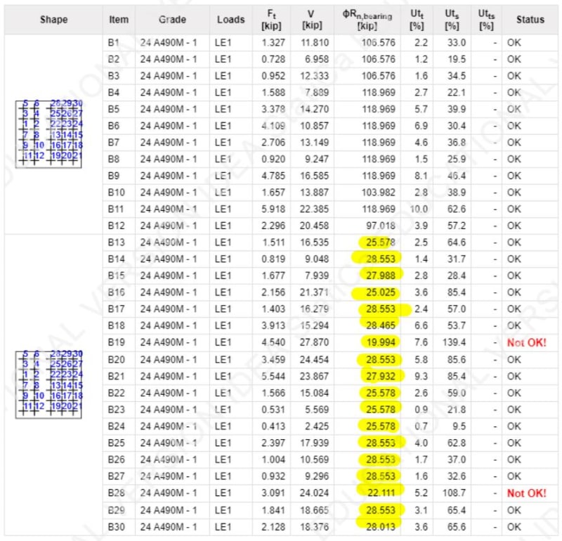
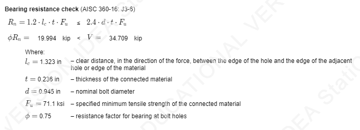
Anyway, my question is that would having web doublers work against this problem? What I would normally do is to find bolt forces due to axial+shear+moment (from eccentricity), check it against the thickness of web + doubler plates and be done with it. Depending on the how much thickness I require, I would use that much of doubler plates. However, we recently purchased a connection software, IdeaStatica to see what it does and find out if we could use. We normally do all calculations by spreadsheets by the way. For a specific example, we have 12 mm we. What we get from the software is that thinner doubler plates somehow takes higher bearing force. From strain compatibility,thicker plates should get higher force but it seems program takes bolt bending into account so doublers strained more than the web, hence higher stresses. I know it all depends on the FEM approach, how stuff is modeled there but it still bugs my mind. I could not find a research on the subject. Do you think this approach is realistic? I want to believe that the old way should work but I need some opinions on that. I attached some more pictures to show what I am trying to say. Also I put the calc. file for those who are interested in the subject.
I hope I made myself clear enough. Please do not hesitate to ask further questions. I would be very happy if someone points me to a research on "force transfer from bolts to multiple plates with varying thicknesses" or something similar. (I think I am terrible at finding keywords.)


