Hi everyone,
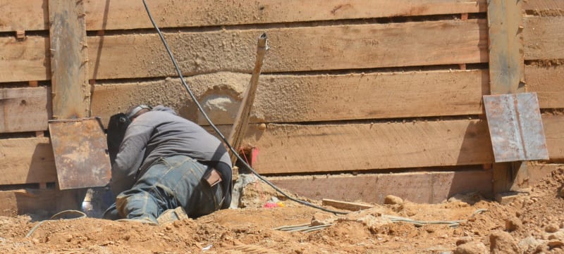
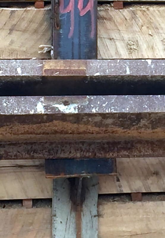
Recently we've had quite a few wedge plates failing when testing our tiebacks (both 25/35 deg). It seems like they're failing due to lateral loading, we're thinking either the piles are misaligned or the tiebacks weren't drilled straight back causing some unintended loading.
We haven't really had this happen in such excess in the past ~10 years of shoring so I've been looking into redesigning them and a little stuck on a straight forward way of analyzing them without just adding small plates to the sides to prevent sideways movement.
We use 3/8" plates currently and I don't really think upping the thickness is going to prevent the movement.
I'd rather not have them weld our walers to them and have to deal with that when removing them after detensioning as well.
Not sure if anyone has any suggestions on how to go about this but anything is pretty helpful.


