Continue to Site

Eng-Tips is the largest engineering community on the Internet

Intelligent Work Forums for Engineering Professionals

  • Congratulations SSS148 on being selected by the Eng-Tips community for having the most helpful posts in the forums last week. Way to Go!

Weld calculation 3

Status
Not open for further replies.

Mr_Curious

Mechanical
Jul 14, 2020
47
Hello everyone.
I am new at weld calculation. And I am looking for an information on how to calculate weld connections properly.
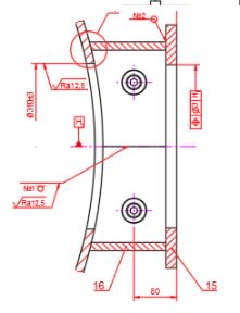
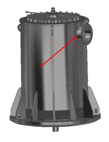
In particular, I have an electric motor with a terminal box that is welded on the side.
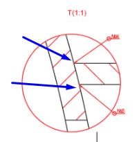
There are two welds, inside and outside of the box. I have tried to calculate it by Ansys, modelling the real weld shape and used mechanical properties of the electrode material but I don't really sure whether this is correct or not.
Could someone share information about how professionals design weld like this?

Thanks a lot in advance.
1_y4kafn.jpg

2_o8d5nf.jpg

3_lnffl7.jpg
 
Replies continue below

Recommended for you

What are you calculating? Cost? Time? Process? Welding filler metal?
 
Seems to me this is a low stress weld with very little load, so acts more like a seal weld than a structural weld. Minimum size and process amenable to production.

 
In any of the design guide, looking for "bevel weld" for details.
 
It is loaded a heavy force. The terminal box is not showed.
 
You need to get the stress around the connection. Then design a fillet weld, pjp weld, or cjp weld to meet the strength demand, with the proper electrode. The design is the easier part of the job, execution can be tricky.
 
You already have decided on the mating parts, how did you dimension those? Especially the short piece of tubing between the housing of the motor and the flange towards the connection box?
 
Hi Gordievsky

We need to see how the welded flange is loaded, ie exactly what is attached to it and it’s mass.
Also what is thickness Of the ring you are welding to the main body? I ask that because you might only need a weld on the outside.
Basically we need a lot more info if we are to help you better.

“Do not worry about your problems with mathematics, I assure you mine are far greater.” Albert Einstein
 
Yes. I just asking about not to get a result here. I want to calculate it by myself and asking about ways i can use. For example where is it better to calculate it Ansys or Inventor and so on.
 
Hi again

I would normally do these calculations by hand Or build the formula into a spreadsheet.

Example calcs can be found here


“Do not worry about your problems with mathematics, I assure you mine are far greater.” Albert Einstein
 
Neither of those, if you can't get at least an approximation by hand.
 
Did you design the welds securing the gussets to face plate and motor body, and the lifting lugs ?
 
Are you an engineering technician or engineer? I don't against the use of computer in design, but you need to know what is your need, and what is the program can provide. It seems you lack that understanding.
 
I am an engineer and i dont know how to calculate it. I will learn how to calculate it by hand, but i think that cad system makes it better because it taking into account complex shapes that can be complicated to calculated by hand.
 
I would get a hold of Blodgett's "Design of Weldments" - a great book.
 
Hi Gordievsky

Weld calculations are fairly straight forward and in your case which appear to be fillet welds they usually take the form of a triangle, the theory behind fillet welds is they always fail on the shear plane , take a look at the link I sent you.

“Do not worry about your problems with mathematics, I assure you mine are far greater.” Albert Einstein
 
Brian's suggestion is excellent, you need to learn the fundamental from the beginning. The, you might be able to model and design the weld once you know the basics.
 
I'd suggest Googling for the article “A Job Weld Done” over on the Autodesk website.

I think it makes a lot of sense.
 
Status
Not open for further replies.

Part and Inventory Search

Sponsor