Continue to Site

Eng-Tips is the largest engineering community on the Internet

Intelligent Work Forums for Engineering Professionals

  • Congratulations SSS148 on being selected by the Eng-Tips community for having the most helpful posts in the forums last week. Way to Go!

Weld calculation 3

Status
Not open for further replies.

Mr_Curious

Mechanical
Jul 14, 2020
47
Hello everyone.
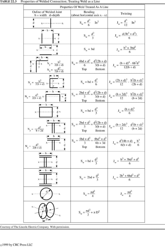
I am new at weld calculation. And I am looking for an information on how to calculate weld connections properly.
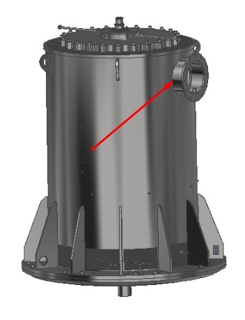
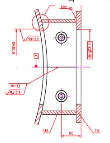
In particular, I have an electric motor with a terminal box that is welded on the side.
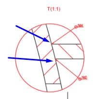
There are two welds, inside and outside of the box. I have tried to calculate it by Ansys, modelling the real weld shape and used mechanical properties of the electrode material but I don't really sure whether this is correct or not.
Could someone share information about how professionals design weld like this?

Thanks a lot in advance.

1_y4kafn.jpg

2_o8d5nf.jpg

3_lnffl7.jpg
 
Replies continue below

Recommended for you

Gordievsky said:
I will learn how to calculate it by hand, but i think that cad system makes it better because it taking into account complex shapes that can be complicated to calculated by hand.

I think you have things backwards.
If you cannot perform a hand calculation (as a sanity check), how will you know if the output from a computer program is reasonable?

(Fill in your favourite computing cliché here__________________________ ...)

"Everyone is entitled to their own opinions, but they are not entitled to their own facts."
 
iron metallurgist said:
I think you have things backwards.
If you cannot perform a hand calculation (as a sanity check), how will you know if the output from a computer program is reasonable?

OP came here from the FEA forum to learn how to validate his FEA results, so I do give him some credit there. However I strongly agree with this. FEA only becomes dangerous when you don't understand the basic theory of design BEFORE making pretty contour plots.

Gordievsky, as BrianE22 mentioned, the gold standard in weld design is Blodgetts "Design of Welded Structures". The special consideration in Blodgett's is that he treats welds as a line with zero thickness, which tends to make design a bit easier.

So Step 1) Calculate shears and moments acting at the centroid of your weld
Step 2) Calculate section properties of weld treated as a line from Blodgett
Step 3) Calculate weld stress in kpi by dividing moments by section modulus and force by area of weld (still treated as a line)
Step 4) Combine vectorially all the forces on the weld
Step 5) Divide the resultant force by the allowable stress to find your required weld thickness

Allowable stress can be found from your design code. It's most likely 2 on yield, but make sure you check. You haven't mentioned what your material is, but if it's normal carbon steel E70 electrode usually works well. Alex Tomonavich has made an excellent spreadsheet called Weldgrp that you can google and download for free that I would use to check your work, since you are so new to weld calculations and mistakes can easily be made.

I am definitely no expert, just some guy on the internet, so please, please do yourself a favor and pick up a copy of Blodgett's Design of Welded Structures and give the relevant sections a thorough read, check your design code for allowables and further guidance (such as the correct filler metal), and check your work with an established spreadsheet.

See Blodgett's Weld Treated as a Line Section Properties below

Blodgett_s_Weld_Treated_as_a_Line_bybp8b.jpg
 
OP said "I have tried to calculate it by Ansys, modelling the real weld shape and used mechanical properties of the electrode material".
How are you modeling undercutting and porosity and microcracking of the weld toes?

Is your motor's junction box loading static or dynamic (fatigue).
A subsequent poster said "Allowable stress can be found from your design code. It's most likely 2 on yield, but make sure you check. "

The state of residual stress of as deposited weld metal is often close to yield, by definition.

The geometry of a fillet weld that is best at resisting cold cracking is concave to provide material for the weld to slurp from during solidification and bend during shrinkage.
The geometry that is best for a stress relieved weld's fatigue resistance is concave with gorgeously detailed weld "toes." More than one study has concluded that weld toe geometry and material soundness is so important it overshadows weld filler material and pretty large variations in weld size.

Often the significant time and expense of converting decently good quality but highly variable as-deposited welds into the optimum weld is completely unacceptable.
In any case, I would compare my weld model stress results to the well accepted empirically derived weld stress allowables appropriate for the part's manufacturing and service loads.
 
TMoose,

All good points.

Design is not just pictures and stress calcs. Material selection, including consideration of the alteration of characteristics through processing, is an integral and essential aspect of design. Not to mention fabrication strategy - are we planning a one-off or 250,000 units?

"Everyone is entitled to their own opinions, but they are not entitled to their own facts."
 
To follow up on Tmoose's comment. My post laid out the basics of weld design with no fatigue considerations. The rest of the weld detailing referenced is beyond my expertise, hence my disclaimer "I am not an expert", just a lowly SE :).

Interesting note about residual stresses of welds being close to yield. Is there some explanation as to why applied stresses aren't additive to that? These are the types of reason I strongly urge NOT TO USE FEA for weld calculations unless you are an absolute expert. Even experts in the field have trouble correctly modeling the welded joint, especially if fatigue considerations are needed.
 
Hi Megastructures,

You asked "why applied stresses aren't additive to (the residual stresses in as deposited weld stresses)?

Once the yield strength is reached it is pretty difficult to increase the stress. The material just continues to yield.
That is why welds are likely to have residual stress ~equal to the yield strength. As the weld cools and shrinks it tries to pull harder against the powerfully restraining surrounding material.
The weld shrinkage forces are powerful and do not go away. Something has to happen to achieve equilibrium.
1 - If the entire weldment is not firmly fixture and restrained the weld shrinkage forces have no difficulty dragging components out of alignment to achieve equilibrium.
2 - IF the entire weldment is restrained the weld just continues to yield until the shrinkage stresses decrease to the yield point. How could it be any other way ?

I am pretty far from a stress analyst But this is where I would start.
If the loading is such that some of the ductile material stress reaches the "yield point" it , well, yields.
This could be in a small portion of the part, or in a simple tension test the entire cross section.

When the load is removed, the elongation etc curve follows the original slope, but is offset by the amount of deformation. hysteresis.

For a simple tension test or tightening a bolt once the yield point is reached additional "load" can look and feel like deformation with no higher forces. The bolt suddenly feels soft and just stretches.

For a weld, or most parts with even slightly complex loading, the FEA "hot spots" hopefully indicate small areas of high localized stress that will yield a little bit under loading.
When the load is removed those hot spots //may// even end up compressed by the surrounding material, and be in a residual state of compression.
Thus one time overstress can make a part resistant to fatigue cracking, similar to shot peening's residual compressive stress.

The "strength" of a welded part chock full of residual stresses requires some deep thoughts in my opinion.
 
well, whats the material being welded? heat treatable or not? you will likely need to find some directive on what kind of electrodes are permissible for the material to make sure your meet metallurgical qualifications. Might have to dig deeper to find if heat pre/post treatment is necessary. For the stress analysis, I'd get a hold of Blodgett's welded structures, and maybe Roarks formulas for stress and strain to determine maximum stresses. Welds can probably be fillets for simplified analysis. Off the top of my head, there are few situations where a 5/16 single pass weld all around will not suffice, but I would certainly still check it
 
In mt 30 August post I incorrectly typed this - " The geometry of a fillet weld that is best at resisting cold cracking is concave to provide material for the weld to slurp from during solidification and bend during shrinkage."

Concave should have been convex, but it is too late for editing now.
 
Status
Not open for further replies.

Part and Inventory Search

Sponsor