Continue to Site

Eng-Tips is the largest engineering community on the Internet

Intelligent Work Forums for Engineering Professionals

  • Congratulations waross on being selected by the Eng-Tips community for having the most helpful posts in the forums last week. Way to Go!

Weld design resistance of moment connection

Status
Not open for further replies.

Finite_element

Civil/Environmental
Mar 9, 2018
6
Looking for any insight on checking existing weld resistance of a moment connection. Basically a small beam with a small span welded at both ends, I want to make sure the ends can be modeled as fixed connections. I need to check the existing weld capacity to make sure this is possible.

LRFD design
I'd imagine AASHTO 6.13 would have it but I can't seem to find specifically for moment resistance. Should I be looking somewhere in AISC?
Thanks for any insight.
 
Replies continue below

Recommended for you

A sketch might help as I'm not sure what you mean by moment connection when you only describe the bottom flange being connected to anything.


Check out Eng-Tips Forum's Policies here:
faq731-376
 
If only the bottom flange of the beam is welded, you do not have a moment connection.
 
The moment capacity of the welds is the strength of the weld metal multiplied by the section modulus of the weld throat about the axis of rotation, generally the neutral axis of the weld perpendicular to the beam. For welds along the sides of the beam flanges, it would be the section modulus for a rectangular cross section about its centroid (S = b*d^2/6, where b is the combined throat depth of the weld and d is the weld length). It it's welded across the ends of the base plate also, add Ad = b*l*d, where l is the length of each transverse weld and b is the weld throat and d is distance between the centroids of the 2 transverse welds.
 
dauwerda said:
If only the bottom flange of the beam is welded, you do not have a moment connection.

I second this. Too much flexibility in the system to be an effective moment connection.

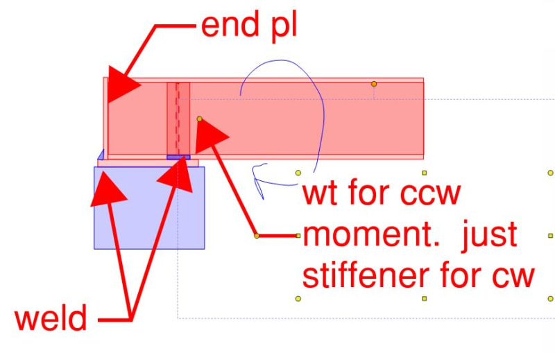
The sketch below shows what I feel would need to happen to call this a moment connection above the bearing plate. Zero chance you've got this without modifying it.

If you have very small loads and deflection isn't important, you might be able to make it work with just flange welds for ULS. You'd need to keep your assumptions intelligent and conservative though in order to prevent an unzipping failure in the welds.

If this is AASHTO, also be mindful of fatigue issues.

c01_pme8il.jpg


HELP! I'd like your help with a thread that I was forced to move to the business issues section where it will surely be seen by next to nobody that matters to me:
 
The OP apparently deleted the entire original question -

Check out Eng-Tips Forum's Policies here:
faq731-376
 
JAE, it turns out this person is also in my class asking for guidance about it last week LOL.
-Research group working with StruCalc software.
We are close to disbanding this endeavor all together due to the complexity of checking this connection.
For anyone interested, here is more discussion on it.


Thanks for all the input.
 
What? So now I've wasted two good sketches on homework? You guys best be setting aside some of your student loans for KootK-Comp.

HELP! I'd like your help with a thread that I was forced to move to the business issues section where it will surely be seen by next to nobody that matters to me:
 
Not homework. It is a real issue.
Even with the welded stiffeners as you propose, the calcs to prove it works and can be considered fixed might be too complicated.
 
Status
Not open for further replies.

Part and Inventory Search

Sponsor