Continue to Site

Eng-Tips is the largest engineering community on the Internet

Intelligent Work Forums for Engineering Professionals

  • Congratulations waross on being selected by the Eng-Tips community for having the most helpful posts in the forums last week. Way to Go!

Weld Material Overstrength

Status
Not open for further replies.

WesternJeb

Structural
Sep 14, 2023
270
Is anyone aware of a material over-strength factor for 70 ksi welding rods? Something similar to how ASTM A992 steel has an Ry = 1.1 and Rt = 1.1 that is published in AISC 341 but I can't find anything on welding rods.

I am needing to design a component to withstand the full strength of a weld to failure and want to make sure that I am including any material overstrength.
 
Replies continue below

Recommended for you

It would be better in that case to design the base metal to fail before the weld. Either use a full pen or beef up your fillet.
 
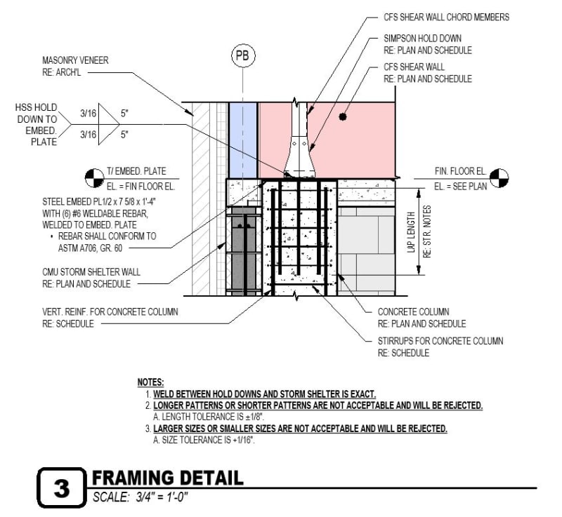
@canwesteng, I agree under every other circumstance. However, I am designing a host building component to separate from the storm shelter wall and am welding some simpson hold downs to an embed. plate in a storm shelter. I believe the hold downs will fail before the welds, but my office all agree that we should still design the embed. plate and load path thereon for the full force the weld could develop before rupturing. See detail below.

Capture_k53w1o.jpg
 
I think welds are too variable to try to impose a maximum strength like this. It's better to use a more predictable failure mechanism as the "fuse" (like yielding of the hold-down or chord), and design everything else (welds and embed) with overstrength factors to ensure failure occurs at the fuse.
 
I agree with the others. That's already a beefy embed connection. Assuming the rebar tails are fully anchored/developed (please let's not trigger another anchorage vs. development saga), that connection has like 140kip-ish capacity just looking at (6) #6 steel strength. The 10" of 3/16 weld has like 40kip capacity. I can't imagine the CFS hold down is rated for much more than that?
 
bones206, the nominal capacity of the hold downs I am using is 86 kips in tension and I am putting a 1.2 factor on that to include a safety factor. The nominal capacity of the welds I am sizing are meant to match/exceed the nominal capacity of the hold downs. The full intent is to develop the fuse and make sure the hold down fails before the welds do but, unsurprisingly, some crazy stuff can happen in a tornado so we are just wanting to cover all bases.
 
dold,
Nominal capacity (as posted by Simpson) is 43 kips apiece, or 86 kips. That was the average value at failure, so I am putting a 1.2 factor on that for a total nominal load of 103 kips. I agree that 140 kips is much larger than this and it should be fine, but just wanting to get some numbers to justify the same calculation for the welds.

The LRFD design load of each hold-down is 28 kips and my demand is 55 kips (seismic with overstrength). They just have a little over a 2 safety factor built into those capacities so the nominal strength is much higher.
 
How thick is the simpson hold down? 75% of the thickness is your leg size.
 
In chapter 7 of AISC DG 26 for blast design, it is recommended to increase design yield stress by 1.2 and design rupture stress by 1.05 for bolted or welded connection design. These simplified design factors consider the dynamic strain effect, which would be applicable in tornado loading, but do not include any material strength increase factor.
 
Status
Not open for further replies.

Part and Inventory Search

Sponsor