Eng-Tips is the largest engineering community on the Internet

Intelligent Work Forums for Engineering Professionals

Weld size parameter "c" in ASME VIII Div.2

Status
Not open for further replies.

CrisDom

Mechanical
Apr 25, 2019
22
0
0
IT
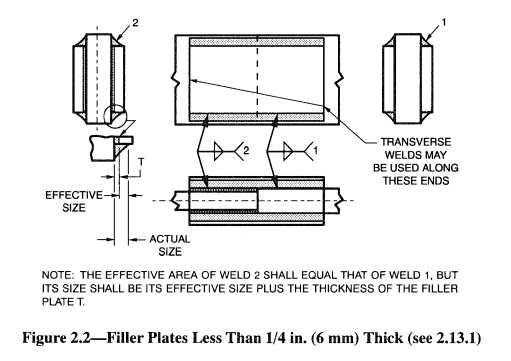
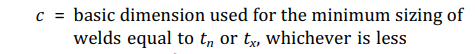
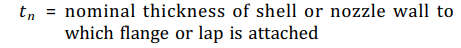
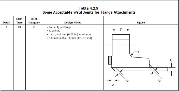
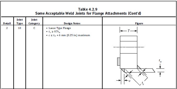
I've a doubt relevant to the meaning of parameter "c" shown in Details 1 and 2 of Table 4.2.9 of ASME VIII Div.2.
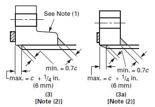
The sketches use "c" to indicate the leg of the weld, but I've a doubt it should refer to the flange offset, since the limit is "similar" to the one specified in Div.1 for the flange offset (refer to fig.2-4 sketches (3) and (3a)).
My doubt is also due to the fact that the triangle used to represent weld is equilateral, so how could "c" be greater than "tn", being it allowed to be =tn+6mm?
Moreover the weld dimension is determined by "tc", so "c" should not be referred to the same weld.

Can anybody give me his/her opinion?

Thanks to all!

Regards

Cristiana
Table_4.2.9_detail_1_vbjnoj.jpg

Table_4.2.9_detail_2_dpjwud.jpg

Fig.2-4_sketces_3_3a_y5pxtg.jpg
 
Replies continue below

Recommended for you

Dimension c has no relation to any other sketches or the dimension 'tc'.

The weld leg runs to the edge of the flange.
Throat thickness tc shall be greater than 0.7tn, which essentially means that both leg lengths including 'c', shall be at least than tn.
The weld leg has length 'c' can be as long as Tn+6 mm.

If c were to be Tn+6 mm, this would result in a slightly elongated weld. What's the problem with that?
 
My doubt is essentially related to the interpretation of ASME VIII Div.2 Table 4.2.9 Figures:
Is the maximum value "cmax=tn+6" to be referred to weld leg (as shown in Tables 4.2.9 sketches) or to max offset?
Even though Table 4.2.9 uses "c" to indicate the weld leg, I think this is not accurate, since "c" should indicate the offset (as done in Fig.3 and 3(a) of ASME VIII Div.1 App.2).
So the limit of "tn+6" should be referred to the offset.
Since I have to implement this requirement on a calculation sheet, I'd like to interpretate Code correctly and to be sure of my understanding.

Thanks for your feedback.
 
CrisDom
1)I mentioned ASME VIII 1 Figure 2-4 (8) to show a difference from other sketches. Here “c” is the fillet throat and “c” is the leg of partial penetration weld. Be careful in the calculation sheet.

2)ASME VIII 1
“tn +6” in Figure 2-4 (3) is the offset
“tn+6” in Figure 2-4 (3a) is for unequal legs

Regards
 
Dear r6155,
I caught your point.

However, I think Div.1 App.2 sketches are quite clear.
Moreover App. 2 clearly defines "c" value as the smallest between tn and tx.
So, based on the numerical value of "c", you can determine the min dimensions for welds (case by case, depending on specific sketch).

My doubt is actually relevant to Div.2 loose flange attachemnt sketches, for different reasons:

[ul]
[li]"c" is not numerically defined, but it's just limited to a max value.[/li]
[li]"c" is used to quote a dimension that, in my opinion, should be unequivocally be referred to the offset between the flange and the cylinder where the flange is attached (as done in details 3 and 4 of Table 4.2.9), whereas in details 1 and 2 "c" is used to quote the leg of the weld and I think this is misleading.[/li]
[/ul]

Regards
 
CrisDom
ASME VIII 2
Table 4.2.9 Detail 2: dimension "C" is incorrect, the text does not match the drawing.

tc > tn it is impossible for inside fillet weld. Notation must be tc=tn not tc ≥ tn

Additional comment: In my specification for pressure vessel only welding neck is allowed.

Regards
 
goutam freelance,
I agree with your safe option, but I just would like to know the correct interpretation of ASME sketch.
You know that Code is Code, so it would be hard to say that something is wrong.

r6155,
I agree with you that Table 4.9.2 Detail 2 is wrong, but is there any official statement or interpretation (I didn't find any) or errata corrige to use as justification to procedd assuming that "c" should be referred to the offset and not to the internal leg length?

Thanks to all

Regards
 
CrisDom
Apply "design notes" in Table 4.2.9 c ≤ tn + 6, not the figure in detail 2
No one can deny the error in the figure.

Regards
 
"c <= tn+6" is for max offset, however the leg length can be elongated to the flange edge if desired. leg length >= tn to achieve tc > 0.7tn.

The dimension 'tc' on 4.2.9 Detail 2 just looks wrong. What is the allowable angle of the tc dimension? I assume 45°?
 
The figure is pretty theoretical – it depicts an equilateral triangle – whereas a real weld is never flat, is either concave or convex

For strength calculations, we’re interested in the throat thickness

The leg size is the length of the legs of an imaginary triangle that can be inscribed within the actual weld for both a convex and concave fillet weld.

In the case of the convex fillet weld (try to avoid) the measured leg is equivalent to the size. In the case of the concave fillet weld the measured leg provides an untrue measure of weld strength which is why these welds are instead assessed based on throat dimension to determine effective weld size.

@ DriveMeNuts: not angle is measured.
Avoid fillet weld unequal legs: waste time and material, and can produce distortion of the flange.
See in internet instruments to measure fillet welds

Regards

 
CrisDom said:
I agree with your safe option, but I just would like to know the correct interpretation of ASME sketch.
If you see the definitions (in Div-1)
image_ojuxpr.png
:

So 'c' is related to weld size and not related to offset.
Now:
image_blz0b1.png

And t_x is more than t_n. So c=t_n.
Throat size t_c>= 0.7c.
Vertical (wrt figure)weld size is t_n
Horizontal weld size c is defined again. The final c<=t_n+6.
So you have the option of unequal leg length.
It makes sense to use smooth transition of flow at weld to reduce erosion and flow disturbances. So if you are not apprehensive about thermal distortion etc. (likely to be less as filled welds have partial penetration) you should prefer smooth transition.


Engineers, think what we have done to the environment !
 
You're referring to Div.1 for definition of "c", whereas my doubts are relevant to Div.2, where "c" is not clearly identified.
So I think it's better to split Div.1 and Div.2, in order to avoid confusion, since symbols and definitions are different.

Moreover I don't agree with you when you say that tx > tn, since, in case of loose flange, tx can be < tn.

At the end, I think "c" should be referred to offset in Div.2; assuming that, all the other symbols/limits seem to be coherent, including the fact that the internal weld can have different leg size.

Thanks to all.

Regards
 
Status
Not open for further replies.
Back
Top