Continue to Site

Eng-Tips is the largest engineering community on the Internet

Intelligent Work Forums for Engineering Professionals

  • Congratulations waross on being selected by the Eng-Tips community for having the most helpful posts in the forums last week. Way to Go!

Weld Sizing - Blodgett vs. FEA 2

m_ridzon

Mechanical
Sep 18, 2020
101
Folks, my project is actually a mechanical engineering project, but I think my question might be suited for this structural forum instead. I've not done much weld sizing in my career, but am now deep into Blodgett's Design of Weldments for an overhead crane I'm working on. It has various fillet welds around its frame. Blodgett's method presents the weld as a line with an allowable force/length. I have two main questions to start:

  1. I was told that the allowable force/length is equal to 0.707*allowable stress. See an example in the image below. It's unclear to me the rationale that is applied to say the allowable force/length is merely 0.707*allowable stress.
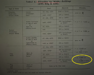
    Blodgetts_Table of Allowables.png

  2. I'm doing most of the work in FEA with shell bodies since the weldment is too complicated to do by hand. I have lots of FEA experience. The customer has requested that we prove our FEA weld sizing method by comparing an example model to hand calcs. I have run a couple of the textbook weld examples found in Blodgett's and other machine design books. My FEA weld stress is not coming close to that of the hand calcs. Below is one example from Blodgetts that I ran in FEA. His allowable force is 9600 lb/in, which correlates to 13600psi (9600 / 0.707). My FEA weld leg is 0.368" but the stress is roughly 70000psi in the root. I was expecting FEA stress near 13600psi. Can anyone share some feedback on this? I don't know how to correlate the FEA to hand calcs. I'm also open to tips on how welds are typically modeled and sized when FEA is used.
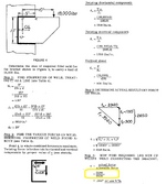
    Blodgetts_Example Problem.png
 
Replies continue below

Recommended for you

The stress peaks in your FEA analysis are spikes and they arent going to correlate with the average stress over the effective throat in the classical method

For the peak FEA stresses to match the classical methods you would need to employ some very advanced modelling.

You should be extracting/integrating the loads from the FEA results to design the welds rather than trying to limit the peak node stresses.
 
Last edited:
You should be extracting/integrating the loads from the FEA results to design the welds rather than trying to limit the peak stresses.
In practice, how is this done? I know how to extract loads at the FEA connections. But on a complex weldment, how do I determine what portions of the loads are creating tension, twisting, torsion, bending, etc., to thereby use the correct hand calc equations? Additionally, the extracted FEA load will be the total load over the entire connection, not per unit length.
 
I'm not an expert in weld design, but here's some quick feedback:
I was told that the allowable force/length is equal to 0.707*allowable stress.
Seems to me this should be 0.707*(allowable stress)*(weld size). If the weld size is equal to both legs of a right triangle (normal assumption), then 0.707 times the leg length would be the shortest length (root) whereby the weld could fracture. The above expression would only be correct if the weld size is 1" (which I'll guess is not the case).

In general, Blodgett is a great resource but I would probably be basing my calcs. on AISC 360 instead. I would expect the two to agree within a reasonable margin though.

Based on the values from the table above that you circled in yellow, I think you should be using an allowable force per length equal to 11,200 * (weld size), which for the 0.368" weld is 4,120 lb/in. (and per AISC I get about 5,460 lb/in).

If your FEA is arriving at a stress of 70,000 psi, it would seem that your design is significantly overstressed, or perhaps there's a stress riser in the FEA (as noted above). This seems much too high though. If you're basing the FEA on an allowable stress of 70,000 psi, then it seems you would be basing the strength strictly on the strength of the weld electrodes, which is not correct. Per AISC, the available stress is roughly 0.60FExx/2 where the value 2 is the omega (safety) factor. For 70,000 psi electrodes, this stress should then be 21,000 psi (again per AISC). It appears the same value is 15,800 psi in Blodgett.

Also, even if your model is too complicated to perfectly model by hand, you should find an approximation. Relying on FEA (or any software) without being able to manually check is really dangerous.

Hope that helps.
 
Please show your FEA mesh and the local stress state at the welds.
Are you just modeling with plate elements? Or trying to actually model the weld fillet?
 
It’s that. He’s reading a singularity, which is invalid.
I haven't modeled anything like this in FEA, but I would have thought a stress riser of more than 10 times over allowable isn't normal.

Based on Question 1 by OP, I doubt this is the only issue with the model.
 
I'm not an expert in weld design, but here's some quick feedback:

Seems to me this should be 0.707*(allowable stress)*(weld size).
Yes, your inclusion of weld size is correct. In haste, I left that part out, assuming it to be understood.

In general, Blodgett is a great resource but I would probably be basing my calcs. on AISC 360 instead. I would expect the two to agree within a reasonable margin though.
Yes, our team is getting into AISC 360 later. We're starting with the basics in Blodgett though, in that welds can be treated as lines and checked for allowable force/length. We are trying to correlate FEA to hand calcs.

Based on the values from the table above that you circled in yellow, I think you should be using an allowable force per length equal to 11,200 * (weld size), which for the 0.368" weld is 4,120 lb/in. (and per AISC I get about 5,460 lb/in).
My apologies, but I may have confused the situation. In my mind, question #1 and #2 were not meant to be correlated to each other in this thread. The allowable for my question #2 is 13600 psi (9600*w lb/in). That's what Blodgett used in his example.

If you're basing the FEA on an allowable stress of 70,000 psi, then it seems you would be basing the strength strictly on the strength of the weld electrodes, which is not correct.
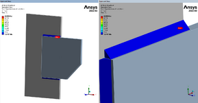
I'm not basing the allowable on the electrode strength. My mention of 70000psi was purely coincidental with electrode strength. Note my images later of the FEA model showing almost 70000psi stress.

Also, even if your model is too complicated to perfectly model by hand, you should find an approximation. Relying on FEA (or any software) without being able to manually check is really dangerous.
Agreed. That's why I'm here trying to understand weld sizing better.

It’s that. He’s reading a singularity, which is invalid.
Correct. It's a singularity and is invalid. But that aside, I'm still trying to understand how to correlate weld sizing FEA to hand calcs.
 
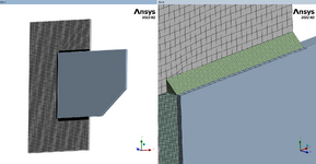
Please show your FEA mesh and the local stress state at the welds.
Are you just modeling with plate elements? Or trying to actually model the weld fillet?
I'm modeling solid bodies. I wanted to do plate elements, but I was concerned the correlation between FEA and hand calcs would be worse. So I was trying to prove the correlation to myself first with solids. Later I plan to attempt plate elements.

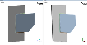
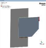
Here are two solid rigid bodies connected with welds. I modeled the welds with leg size 0.368" to imitate Blodgett's example. The load is 18000lbf, same as Blodgett's. Stress is almost 70000psi in the root of the weld(s).

Blodgett_Model 1.png

Blodgett_Model 2.png

Blodgett_Model 3.png

Blodgett_Model 4.png

Blodgett_Model 5.png

Blodgett_Model 6.png
 
ok, as I suspected, two completely different analyses.
if your plates are fully "rigid" then the model is completely unrealistic.
then, the very detailed stresses in the weld cannot be compared to the hand calc at all; the hand calc uses an averaged stress over the weld.
a more appropriate model would use shell element for the plate, with realistic mateiral properties, with the welds modelled with connection elements between the plates. then you extract the forces from the connection elements, convert to running loads (normal, shear) and compare to the hand calcs.
Hmm, I'm confused on how a less-accurate modeling method (i.e., plate elements) would produce better correlation with hand calcs. I'm also confused on how the rigidity of the plates play a part in the calculation. Blodgett does not mention the thickness of his plates. Potentially, they could be very oversized (e.g., 2" thick) and behaving as rigid like my FEA model.

That said, I'm going to try a plate model on Monday when back at the office.
 
Because numerically a perfectly rigid plate is very different from a thick steel plate (infinite vs finite stiffness).

And you don’t need detailed stresses inside the weld; you just need forces along the weld length; hence why a plate model is easier and more appropriate.
 
Also even if you ARE modelling welds then without plate models then your need to account for singularities and some plastic behaviour if you are delving into meshes this fine.
 
The classical analysis does assume the plates are fully rigid, so that isn't the problem. You have the following problems in the FEA -
1. You seem to be looking at the stress at the root and not over the average of the weld. This is incorrect. All equations for weld capacity are based on an average stress over the weldment.
2. You are using von mises energy criterion and not principal stresses. Von mises is for ductile elements, and also, it will bump up the value of the stress you see given there is a shear component (the root 3 tau component of VM yield criterion). You can see this in the AISC 360 equation for shear capacity, there is a ~0.6 factor to account for the conversion of shear stresses to a value we can compare to the tensile yield of the material. This apparent bump up of apparent stress with shear vs tension is captured in the AISC equations for the weld strength already (again VM is a yield criterion not strictly a stress, and principal stress is more relevant for brittle elements like welds)
3. Like everyone said, this needs to be resolved using AISC 360 or the steel code in force in your jurisdiction, FEA is not appropriate for this. Consider also buckling of the plate if it is unstiffened as shown, equations for this are also available in the AISC manual (possibly in the spec). I've never used Ansys but most FEA doesn't capture inelastic buckling, which will be what happens here.
 
Why one would mesh a weld for a connection like this is beyond me. We did short, understandable and easy calculations for this (see Blodgett) in college.

FEA isn't best used for everything.
 
FEA isn't best used for everything.
and when you use it you have to be careful about what you are doing. FEM can give wildly different answers.
 
Last edited:
Why one would mesh a weld for a connection like this is beyond me. We did short, understandable and easy calculations for this (see Blodgett) in college.

FEA isn't best used for everything.
Hence why the customer was asking for hand calcs.
 
For a weld in shear across the throat:

S = F/A = (F/L)(L)/((.707w)(L))

Where S is stress
F is total force
F/L is force per length of weld
L is length
w is weld leg size
0.707 is throat size for equal leg weld

Solve for w in terms of allowable stress Sa

w = (F/L)/(.707Sa) where .707Sa is allowable force per unit length
 

Part and Inventory Search

Sponsor