Eng-Tips is the largest engineering community on the Internet

Intelligent Work Forums for Engineering Professionals

Weld Stress Analysis 1

Status
Not open for further replies.

Gowrath

Mechanical
Jan 8, 2010
17
0
0
CA
I've analyzed a jib crane design analytically and via FEA. The FEA results do not match up with the analytical calculations.
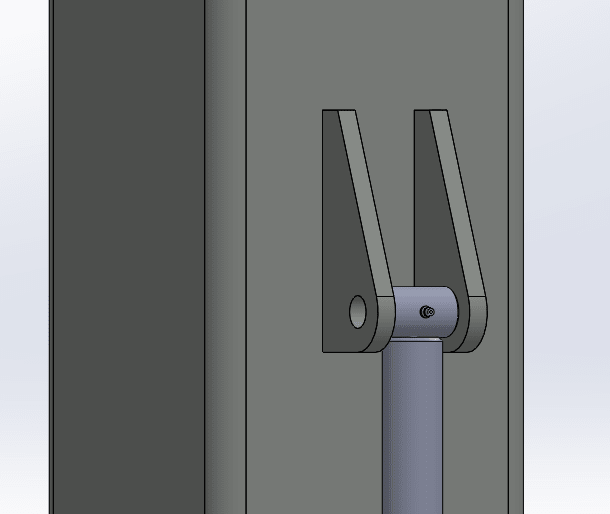
For example, when analyzing this connection between a piston and a post:
piston_vz0ky9.png

I assumed this weld pattern:
weld_adalhk.png

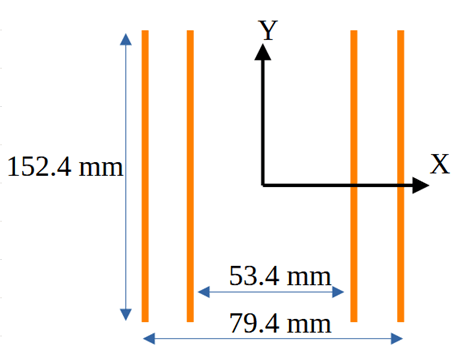
with the welds being 9 mm fillets.
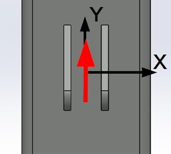
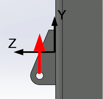
The connection is loaded vertically, with the load being offset from the weld pattern:
frontweld_zhg3vh.png
side_zeh6ia.png


I calculated the primary and secondary shear stresses on the weld pattern and found the max stress (at the top/bottom of the weld pattern) to be 3.4 MPa.
I assumed a E60xx weld electrode with a yield strength of 345 MPa. I assumed a shear yield strength of 50%. My calculated load factor was therefore 50.

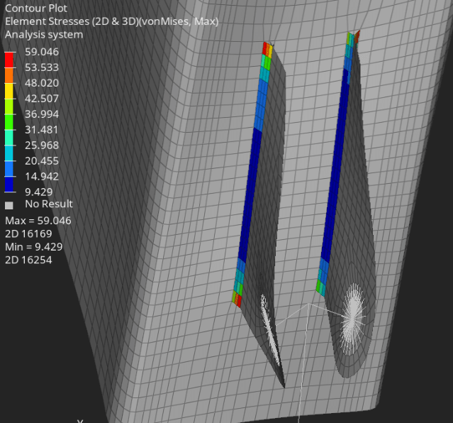
I then simulated the structure and found stress values that were an order of magnitude larger than calculated:
fea1_q9dcf4.png


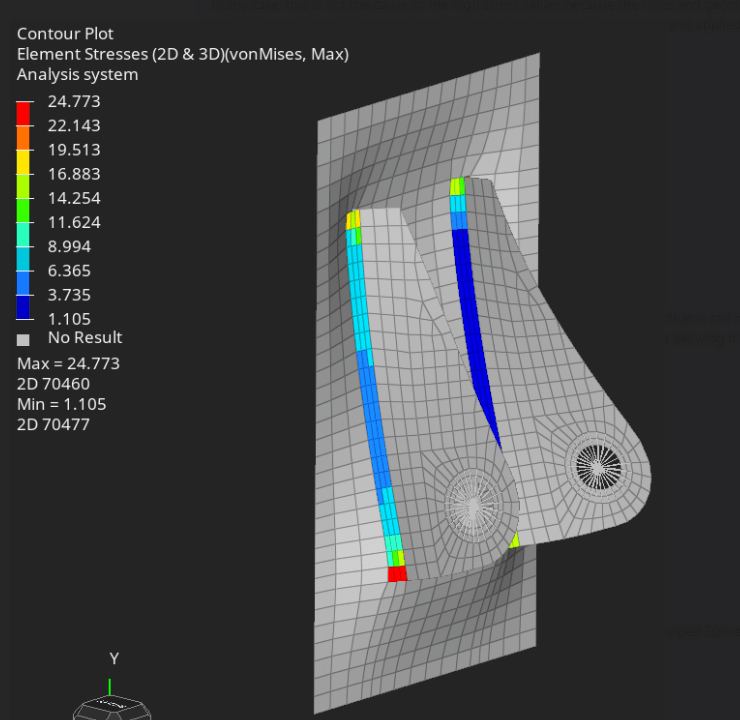
I isolated a small section around the connection and simulated it with the backplate (section of the post) fixed at the edges:
fea2_rdzaz8.png


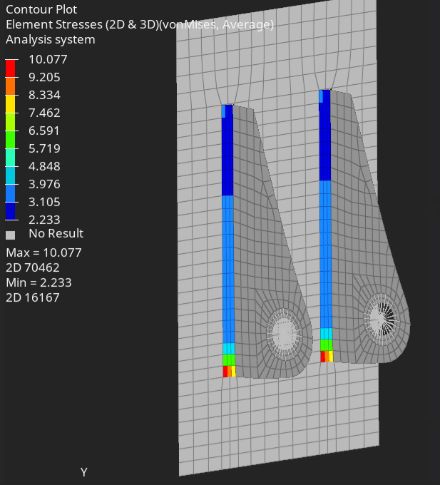
I simulated the section again, but constrained the entire face of the backplate. The stresses again dropped by 50% but were still much larger than calculated:
fea3_jklify.png


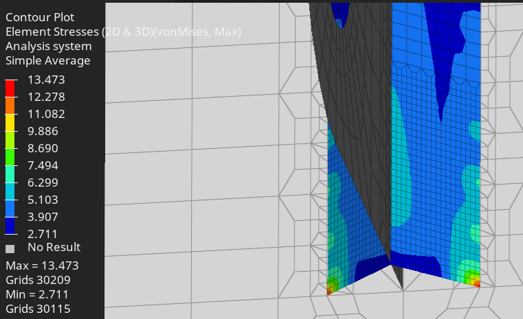
After mesh refinement, the large stress value is concentrated in the corner(s). The stress values adjacent to the corner are closer to the calculated values, but still higher:
fea4_avy0tp.png


So the FEA simulation is obviously dependent on the stiffness of the welded components, but the analytical calculation doesn't take this into account, and only considers the weld pattern properties and the loads on the pattern.
What am I doing wrong and/or how do I reconcile the discrepancy between the calculated and simulated results?

Thanks.
 
Replies continue below

Recommended for you

The FEM has a singularity at the corners, producing high stresses which will increase as you refine the mesh. In reality those corners are not sharp. Also the material can yield slightly local to those corners.

FEM = a numerical approximate solution to an approximate idealization of reality.
 
Have you checked the internal forces and moments in the connections in your FEA model to see how they compare to your hand calcs? While I agree that this looks like a singularity issue, checking the forces/moments would be a good sense check to make sure there aren't any other errors in your model.
 
Greetings.
This is why you pay for the welding engineers to calculate those amounts due to welding is a special procedure that its quality cannot be guaranteed.
Means : sim will never work.
:>
Simulations calculate perfect conditions . however the real implications of the weld ALWAYS have imperfections.

Simulations on such procedures will give you just some overall opinion. Following standards are the mandatory approach due to they are generated by real tests.

Best regards.


IWE EWE certificate holder.
 
FEA results will rarely (never) match analytical results. They are at opposite ends of the spectrum in terms of precision. In fact, in most cases FEA for connection design is not justifiable. FEA is calculating the stresses to a nano degree of precision while your loads for a jib crane are maybe within 10% of reality if you're lucky. I would put the FEA away and tackle this with first principle mechanics.
 
Why would anyone do an FEM on that... you are looking for problems... AISC, CIDECT and others have addressed longitudinal plates on HSS reasonably well and the weld section properties are real easy... [ponder]

-----*****-----
So strange to see the singularity approaching while the entire planet is rapidly turning into a hellscape. -John Coates

-Dik
 
Hi Gowrath,

Which version of Ansys are you using? I believe you have modeled the weld using the connecting edges whereby Ansys created a weld - user has to input the length and size of weld.

I see that your second/third plot shows a predominant blue region which is of the order of 3 MPa which conforms with your hand calculations with peaks at the corners which you can ignore.

I do not have information on how you have calculated the weld stresses using hand calculations but alternatively, you can refer a book - Design of welded structures by Blodgett. It's a really good book for welding calculations using first principles and there are lot of examples, and you will find a similar problem in that book.

Like dik wrote this is a simple problem and should not require FEA.


Shiraz
Sr. Engineer
 
Gow...

How do you make the two long fillet welds on the INSIDE of your bracket ???

IMHO, they seem to be nearly impossible to accomplish with standard stick welding ... perhaps with TIG ?

This "difficulty to weld" is the reason why a bent plate bracket design is often selected instead of trying to weld and align two individual plates.

My opinion only

MJCronin
Sr. Process Engineer
 
Hi Gorath

I would just add that the hand calculations assume that the stresses in the weld are evenly distributed so the stress the obtained by the formula's are an average stress over the weld.
In my experience provided you use a good safety factor the hand calculations are fine, I have never used FE for weld stresses and I have had no problems with any of the fabrications I have designed over the 50 years I worked.

“Do not worry about your problems with mathematics, I assure you mine are far greater.” Albert Einstein
 
For relatively short langths, weld stresses can safely be assumed as evenly distributed. It's only in longer continuous lengths, that the middle part of the weld doesn't provide much resistance because it's at the ends where the forces act the most. I agree, hand calcs are more than enough for these applications.
@ MJCronin, it appears from the drawing these welds are accessible at a ~45° angle, so no worries there. I've worked with much less reachable welds. There exist GMAW torches for narrow spaces, and you can always bend your rods if needed. Unlikely that GTAW would be used here.
 
00000000000000000000000000000000000000000000000000000001111byoyuvtyvtiiuk_oykkul.jpg


I believe that this is a case where fabrication constraints control the final design ...

I would purchase or fabricate a shop-fabricated gusseted bracket like this ... then specify an "easy to perform" and very inspectable fillet weld aroud the perimeter...

Also in my opinion, I disagree with "kingnero" ... Aside from the aerospace industry, the welding would be difficult

The two "inside" fillet welds described above are only some ~54mm apart ... we do not know many other dimensions.

Anyone agree or disagree with me about gusseted bracket usage ?

MJCronin
Sr. Process Engineer
 
Thank you everyone for your replies.
I can justify hand calculations with safety factors for static loads, like the above example. However, many of the components that I analyze experience dynamic loading that is hard characterize, and a welded component can experience varying loads - either as a whole or in various sections of the weld.
It is these localized varying stresses that initiate fractures that propagate and potentially lead to failure. This is why I am interested in a method of capturing local stress variations within welds (or parent materials adjacent to the welds).
 
Status
Not open for further replies.
Back
Top