Continue to Site

Eng-Tips is the largest engineering community on the Internet

Intelligent Work Forums for Engineering Professionals

  • Congratulations The Obturator on being selected by the Eng-Tips community for having the most helpful posts in the forums last week. Way to Go!

Welded angle bracket 3

Status
Not open for further replies.

bugbus

Structural
Aug 14, 2018
515
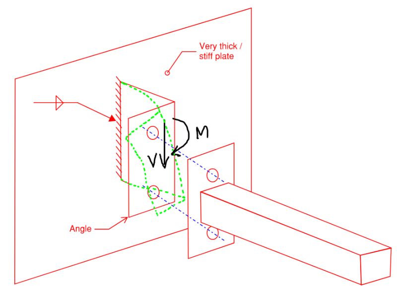
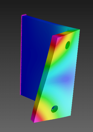
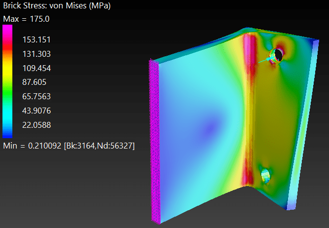
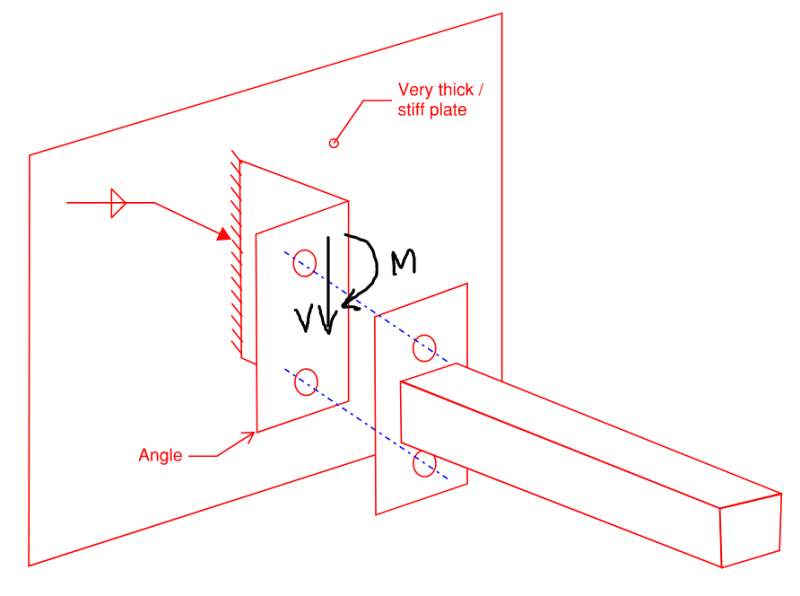
What is the failure mode for a bracket like this? I imagine it is more complicated than it appears, and probably involves some kind of twisting action.

I wonder if there are any design guides or if anyone has prior experience?

Capture_ucv2vn.png
 
Replies continue below

Recommended for you

Capture2_iqja78.png


The green lines are showing how I imagine the angle to deform.
 
After thinking about this some more, here's what I have done:

1. Resolve the forces through the connection and the two plates of the angle
2. Calculate average shear stress = V /(b*h)
3. Calculate maximum bending stress = (M + V*leg length) / (b*h^2/6)
4. Calculate maximum torsion stress = (V*leg length/2) /(0.333*b*h^2)
5. Calculate resultant shear stress as (2) + (4)
6. Calculate von Mises stress at point of maximum bending, noting that including the shear stress in (5) is conservative since the maximum shear and torsion stress occur at the mid-height of the plate
7. Compare (6) with the yield strength of the angle.
8. Check weld strength similar to the above approach.

In addition to all this, perhaps there are second order effects that should be considered? The angle is fairly flexible in torsion, and so I imagine that we would either need to limit the rotation to an acceptably small value?
 
Hi gusmurr

In your list I cannot see a check for shear stress in the weld due to bending action, I note you have covered the average shear stress due to the vertical load,

“Do not worry about your problems with mathematics, I assure you mine are far greater.” Albert Einstein
 
If you're open to alternatives...weld threaded studs to your very thick plate. Link
 
Why bother with that, use a channel section. Still can get to the bolts top and bottom. Work smarter not harder.
 
JStructsteel said:
use a channel section. Still can get to the bolts top and bottom.
With the "web" or back towards the horizontal beam, and weld both "flanges" to the thick plate.
Vertically, so no water can accumulate.
 
Can you do a 'knife' plate on your HSS section. Then do a straight extended plate on the wall piece with standard bolt setup. There are lots of design examples for the extended plate. I bet the Steel Tube Institute has an example for the knife plate.

It's a much cleaner load path. Your current drawing has the load twisting and turning through several elements.

Capture_dnnimy.jpg
 
Thanks for the responses everyone.

I agree that the channel makes more sense than the angle. However, the loads I am dealing with are quite small, so I wanted to see if this was feasible with the angle. Anyway, I might progress with the channel option for now.

I also like the welded threaded stud idea, but I need to see how this would work with all the exposed steel needing to be painted.
 
They can mask the areas that need to have studs welded so they aren't coated, or mask the studs themselves when they're sprayed if already attached. Then after everything is installed, touch up paint will take care of any areas outside the area of the end plate that aren't coated.
 

Yes, I do it lots of times... slikker than catsh*t on linoleum... and am slowly getting fabricators to use that rather than an endplate with a plate welded to it.

Rather than think climate change and the corona virus as science, think of it as the wrath of God. Do you feel any better?

-Dik
 
dik said:
Yes, I do it lots of times... slikker than catsh*t on linoleum... and am slowly getting fabricators to use that rather than an endplate with a plate welded to it.

Why do you prefer the knife plate to the end plate with a plate on the end?

I'm just curious as I've always used the knife plate design but have recently found myself questioning the altertive of an endplate as I've seen at a few sites recently and just wondered if fabrication would be easier.
 
It's less costly and faster, and you don't need drain holes and plugs. You don't have to clip the BAR material unless you are entering a double member connection that requires an actual gusset plate... Based on an earlier thread double side plates can be used for a bolted connection and for light loading you can use a simple eccentric connection. You also have to take care of the shear flow... usually using the dimension of the HSS for the plate development length is adequate.

Rather than think climate change and the corona virus as science, think of it as the wrath of God. Do you feel any better?

-Dik
 
Something like (from my SMath program)...

Clipboard01_ystjfg.jpg


Rather than think climate change and the corona virus as science, think of it as the wrath of God. Do you feel any better?

-Dik
 
Thanks. Yeah I prefer knife plates. But I just wanted to ask the question as sometimes our preference are simply dictated by what we are used to rather than good rational reasons.
 
Out of interest, here is what the FE model has to say:

Below is showing the bracket deformation under the actual loading (scaled up 50x). Maximum tip deflection is approx. 0.4 mm (1/64"). Note, this is a 125x75x10 (5"x3"x0.4") UA angle with V ~ 2 kN (450 lbf) and M ~ 1 kNm (740 lb-ft) acting on the bracket.

1_vzy68q.png


Below is showing the Von Mises stress on the inside and outside of the bracket. Ignoring the local stresses around the bolt hole, the Von Mises stress at the inside corner of the bend is approx. 170 MPa (25 ksi). This seems to be the critical part of the bracket, as you will see in the next figure.

2_tfnwlg.png
3_iamhe3.png


Below is showing the yielded regions when the load is at approx. 3x the nominal load above. The solver struggled to get past this point, so it is probably getting close to the collapse load of the bracket. I had not previously considered the shorter leg of the angle 'unfolding' from the longer leg as the critical failure mode. The rest of the bracket is working pretty easily.

4_bvrldg.png
 
@ gusmurr
admire your efforts
could you add a triangular stiffener between the two hole
this will reduce the stress greatly [i think]
 
I suspect a triangular stiffener won't do much and is quite expensive to add.

Rather than think climate change and the corona virus as science, think of it as the wrath of God. Do you feel any better?

-Dik
 
gusmrr said:
6. Calculate von Mises stress at point of maximum bending, noting that including the shear stress in (5) is conservative since the maximum shear and torsion stress occur at the mid-height of the plate

Doesn't the Von Mises stress already include the shear stress component?
 
I agree with dik, between the holes there is not much deflection at all so I don't think the stiffener would help much. Would be more effective at the top and bottom though.

haynewp, yes you're right. My idea was that since the maximum bending stress and maximum shear stress don't occur at the same location, it would be conservative to calculate a Von Mises stress based on these two maximum values as a quick ballpark check.
 
Status
Not open for further replies.

Part and Inventory Search

Sponsor