Eng-Tips is the largest engineering community on the Internet

Intelligent Work Forums for Engineering Professionals

Welded Rebar Embed Plate - Shear Checks 1

Status
Not open for further replies.

efFeb

Structural
Dec 25, 2019
65
0
0
CA
Hi!
I have an embed plate with an infinite wall on all sides that is taking only shear. My shear force is pretty high (this is a girder framing into the end of a wall), and so I am thinking to design an embed plate with 20M rebar welded to lap with continuous 20M bars in the wall.
To check this embed, I used clause 11.5.2 d) of CSA A23.3 with the values of c and μ taken for concrete anchored to as-rolled structural steel by headed studs or reinforcing bars.
When I did this check and compared the shear capacity to the maximum shear capacity for the same condition in Hilti profis, using studs, I actually found that profis gave me a higher value. Is this shear friction check not required for embeds? It does not seem that this is being done in profis.
Any thoughts on this would be very helpful. Thanks so much!
 
Replies continue below

Recommended for you

Two different theories essentially, anchor theory (for embedded studs that primarily rely on concrete to act in tension) and rebar theory where it's more about similar concepts related to development of reinforcement.

For studs it is checking the steel shear capacity of the studs, maybe something like strength reduction factor x 0.6 x A_stud x f_u_stud, which isn't the same as the shear friction check you've quoted for developed reinforcement. Effectively addressing the same thing but in two uniquely different ways conceptually.

Hilti have plenty of web resources outlining the differences between anchor and rebar theory if you do some googling.


efFeb said:
Is this shear friction check not required for embeds?

No, I don't believe that it is. Here's what I think that I know of the history of this, in chronological order.

1) Back in the Flintstone era, we used to assume that some multiple of the anchor was effective in "bearing". 6d or 8d or whatever. Turns out that was complete nonsense. And even if it were not complete nonsense, there were still a bunch of other failure modes that we needed to be checking anyhow.

2) In the early days of modern anchorage theory, you would see shear friction checks done in the literature as you've suggested. The idea, I believe, was to replace the "bearing area" concept as the means of initially getting the shear force out of the plate and into the concrete mass. Unfortunately the shear friction business does not account for the impact of edge distances etc so you still needed a bunch of other failure mode checks as well.

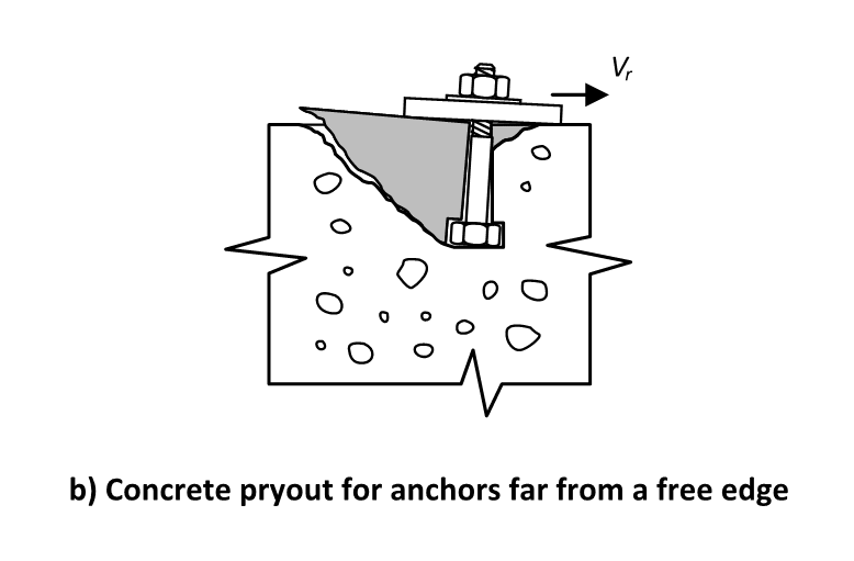
3) We seem to have landed on the failure mode shown below as being the means of initially getting the shear force out of the plate and into the concrete mass. This is really what the "bearing area" concept should have been all along. You never really do generate a true bearing stress failure at any reasonable anchor length. Rather, you get this baby pry out mechanism. I don't recall seeing a shear friction check in the literature in over a decade. But, then, I've not been searching for it either.

4) Testing suggests that DBA capacities are always higher than equivalent diameter HCA capacities. The ratio is relatively constant at about 1.2 for large edge distances and increases for lower edge distances.

5) From experience, I know that the failure mode shown below often does produce a higher capacity than does shear friction. Are there some anchorage arrangements where shear friction is the winner? Maybe very densely spaced studs in low strength concrete? I really don't know. What I do know is that concrete to steel shear friction is thought to be a true "dowel mechanism" of shear resistance to a significant degree. And, in my mind, "dowel resistance" is precisely what the failure mode shown below is speaking to. Consequently, I'd be pretty hesitant to go with the shear friction number even if it did represent an improvement over the baby pry out failure mode shown below.

c01_yk8wwu.png
 
With rebar anchors fully developed and lapped with wall reinforcement like efFeb has stated you're not going to get pryout though? That's more a phenomenon of shallower embedded stud anchors.

You should be checking a steel failure limit state for the anchors themselves, whether studs or rebar.

In my mind there is no reason why you can't use the steel limit states related to stud anchors for reinforcement bars at the interface. The alternative is shear friction.

If you considered instead of having an embedded plate with reinforcement bars welded to the back, that you had a beam extending from the panel with the same reinforcement. We would not be typically checking concrete breakout like we would for 'anchors' in the panel. I guess that's one fundamental point of difference between anchor and rebar theory.

Edit - just for clarity I'm assuming the bars welded to the plate are like 1000mm long or something, not short welded lengths of bar

 
As a side note, if you're doing embedded plates in Canada, go to the Canadian Precast Concrete Institute site and get a free copy of their design guide. The connections section has a bunch of tables and design examples for embedded plates and similar things.

They don't really touch on rebar embeds, but just generally useful.
 
For very large edge distances you will generally shear off fully developed rebar. So check that. Check the welds too, as often they will fail prior to the bar itself.
 
Agent666 said:
With rebar anchors fully developed and lapped with wall reinforcement like efFeb has stated you're not going to get pryout though?

I disagree. With the anchors developed and anchored, you're not going to get a pry out failure of the entire anchor group. I believe that the pry out failure of individual anchors -- what I've been calling baby pry out -- remains on the table as a potential failure mode.

Agent666 said:
You should be checking a steel failure limit state for the anchors themselves, whether studs or rebar.

I agree completely assuming that "steel failure limit state" means things like anchor shear failure, weld failure etc. Hopefully we are all on the same page in recognizing that those failure modes alone are not sufficient for us to have claimed to have moved the shear load into the body of the concrete mass however. For that, we need one of the following in addition to the steel failure checks, depending on one's believe system:

1) Shear friction or;

2) Individual anchor pry out.

Agent666 said:
If you considered instead of having an embedded plate with reinforcement bars welded to the back, that you had a beam extending from the panel with the same reinforcement. We would not be typically checking concrete breakout like we would for 'anchors' in the panel.

Are we talking about a beam mounted to the face of a panel or embedded some distance into a panel? If it's the former, then I absolutely would be checking some form(s) of shear breakout. If it's the latter, then you have direct beam bearing for shear transfer so it's a moot point.

Agent666 said:
I guess that's one fundamental point of difference between anchor and rebar theory.

I feel that we need to be careful with "rebar theory vs anchor theory" in this situation. Here's how I see it:

a) Anchor theory = relying on concrete in tension to move tension stresses around.

b) Rebar theory = relying on rebar to move tension stresses around.

For flexure within these kinds of connections, I agree, the use of lapped rebar is rebar theory.

For shear, however, I would argue that all of the options discussed so far, including shear friction, are still anchor theory. Similarly, I would argue that regular beam shear is also "anchor theory" in this sense unless stirrups are relied upon to resist 100% of the beam shear.
 
This is drifting into the abstruse but I feel that shear friction produces two functional difficulties for these kinds of connections:

1) Quite often, shear breakout edge distances do matter. Where that is the case, one needs to know where the shear gets delivered in order to evaluate the shear breakout. With shear friction, the location of shear friction resistance seems rather vague to me beyond just "in the flexural compression zone". A stiffer connecting plate will push the center of shear resistance closer to any free edge potentially.

2) Almost always, there will be anchors in the flexural compression zone. The presence of those anchors will serve to shield the concrete to steel interface from the very clamping force that is desirable for shear transfer via shear friction. In my mind, this steers the situation back towards true dowel action in the flexural compression zone.
 
Status
Not open for further replies.
Back
Top