question_asker
Structural
Hello. I am looking for guidance/suggestions on a tricky connection for a temporary structure I am designing.
I have attached a sketch of the proposed detail. On this structure, steel pipe pile (24" x 0.5" wall) will be supported by a HP14x73 pile located inside the pipe. The HP14x73 has a stocky angle welded to each flange as a bracket/bearing to "catch" the web of the MC8x20 channel, which is to be welded to the interior of the 24" pipe (in shop). Lateral support/blocking provided elsewhere and not shown. Only concerned about the vertical loads at this connection.
I am concerned about the welding of the MC8x20 to the inside of the 24" pipe. Using AISC SCM 14th Edition, Table 8-4, I determined the available group weld strength to be 34.5 kips. Calculations included with the attached sketch. The required load = 25 k, therefore 25k / 34.5k = 73% utilization, Weld OK. (Everything checked using service loads / ASD)
Interested to know your opinion on the following:
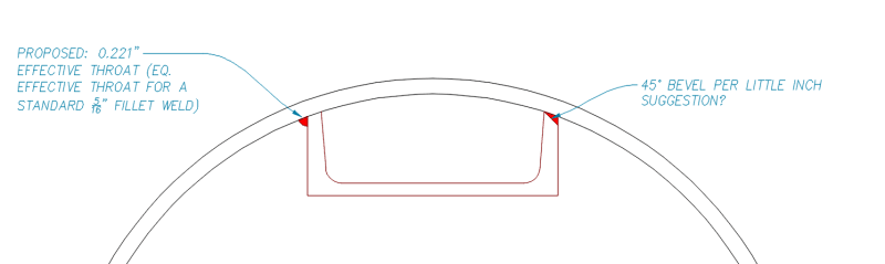
1. Any additional consideration required due to the acute angle of this fillet weld? The dihedral angle is approximately 67 degrees. From my review of AWS D1.1 and the AISC SCM, I did not see any reduction I needed to apply for dihedral angle between 60 and 80 degrees, it is only reduced when the acute angle drops below 60 degrees. Perhaps I need to add a clearer detail to indicate what the exact required effective throat is, although 5/16" legs with an acute angle would exceed the effective throat of a typical 90 degree tee joint and would be conservative.
2. Would you consider adding additional weld to the inside of the channel leg? My concerns about this were that it would be difficult to actually perform that weld, the weld itself would be complicated geometry (something like a flare and fillet weld), and there is a chance that in trying to strengthen the connection it is inadvertently weakened due to the heat output and difficulties mentioned.
Thank you for your input.
I have attached a sketch of the proposed detail. On this structure, steel pipe pile (24" x 0.5" wall) will be supported by a HP14x73 pile located inside the pipe. The HP14x73 has a stocky angle welded to each flange as a bracket/bearing to "catch" the web of the MC8x20 channel, which is to be welded to the interior of the 24" pipe (in shop). Lateral support/blocking provided elsewhere and not shown. Only concerned about the vertical loads at this connection.
I am concerned about the welding of the MC8x20 to the inside of the 24" pipe. Using AISC SCM 14th Edition, Table 8-4, I determined the available group weld strength to be 34.5 kips. Calculations included with the attached sketch. The required load = 25 k, therefore 25k / 34.5k = 73% utilization, Weld OK. (Everything checked using service loads / ASD)
Interested to know your opinion on the following:
1. Any additional consideration required due to the acute angle of this fillet weld? The dihedral angle is approximately 67 degrees. From my review of AWS D1.1 and the AISC SCM, I did not see any reduction I needed to apply for dihedral angle between 60 and 80 degrees, it is only reduced when the acute angle drops below 60 degrees. Perhaps I need to add a clearer detail to indicate what the exact required effective throat is, although 5/16" legs with an acute angle would exceed the effective throat of a typical 90 degree tee joint and would be conservative.
2. Would you consider adding additional weld to the inside of the channel leg? My concerns about this were that it would be difficult to actually perform that weld, the weld itself would be complicated geometry (something like a flare and fillet weld), and there is a chance that in trying to strengthen the connection it is inadvertently weakened due to the heat output and difficulties mentioned.
Thank you for your input.