Eng-Tips is the largest engineering community on the Internet

Intelligent Work Forums for Engineering Professionals

  • Congratulations waross on being selected by the Tek-Tips community for having the most helpful posts in the forums last week. Way to Go!

Welding method choice 3

Status
Not open for further replies.

elinah34

Mechanical
Aug 19, 2014
115
0
0
IL
Are there any instructions how to choose welding technology (MIG, TIG, EBW, etc.) based on the relevant application?
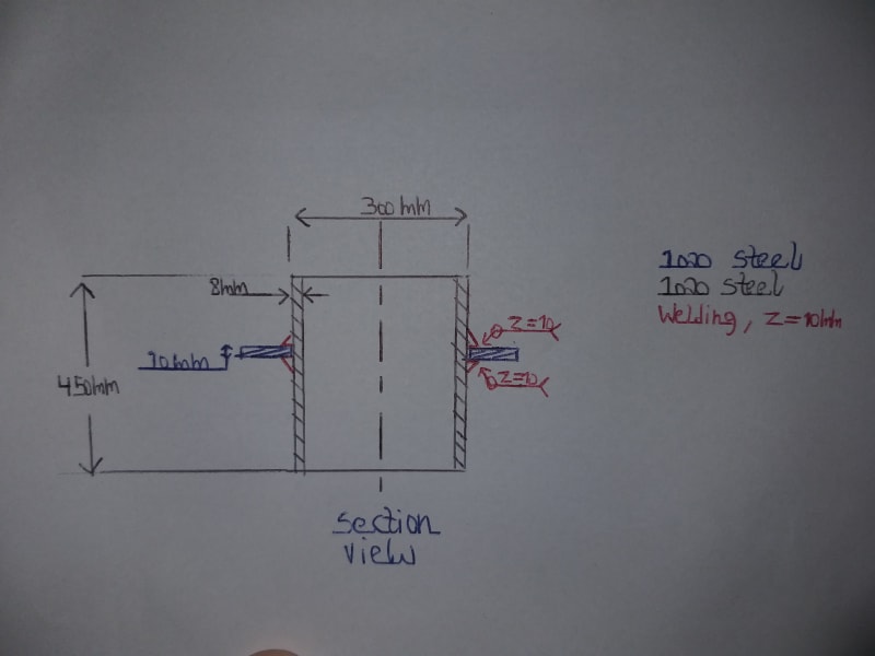
I am designing a structure that should be dynamically (vibrations) tested soon, and I originally instructed to use TIG method.
The workshop prefers to use MIG welding.
I wonder what should I do? I originally chose TIG since I read it's the best quality welding.
But now after being asked for changing it to MIG I really want to deeply understand what the consequences might be.
When learning welding in the university we dealt with the size of the welding by dedicated calculations, but I couldn't find any considerations regarding which technology is best suited for the entire different applications.
 
Replies continue below

Recommended for you

It's largely determined by the materials being welded, the service environment, including load application and costs. AWS Hand Books and the ASM Welding volume. GTAW (TIG) is one of the more expensive proceses, especially manual GTAW. Having no idea what you are welding and its service, I cannot say whether the GTAW should be employed.
 
This part is carried by an aircraft, and its interface is the peripheral (blue) flange/ring.
The applied loads are accelerations and vibrations.
I attached a schematic picture of the part, its bodies and materials.
20211011_220844_iqzzrm.jpg
 
If you are truly concerned with fatigue failure you should make the welds full penetration with reinforcing fillets. Fillet welds in fatigue can have less than 25% of the fatigue life of a full penetration weld. As long as they are not using the short circuiting method of transfer and uses at least a 75% Ar-25% CO2 gas mixture, I would have no problem using GMAW.
 
It'd be a bit odd to have some big assembly with 20 completely different types of welds on it because 20 different designers specced it out and none of them talked to each other. So my first thought, is what's being done on similar pieces that this same shop is fabbing? What's been done in the past? That doesn't mean you have to do it that way, but think twice before you arbitrarily change it, too.
On miscellaneous parts-welding in general, just asking the welder in question "Hey, what's the best way to do this?" can be informative. Shops can vary in the equipment and skills available, and if there's a faster easier way, that'd be the preference unless there is some good reason to do otherwise.
 
Weldstan, what do you mean by reinforcing fillets?
Just to make sure - when (simple) calculations are done the penetration depth isn't taken into account, right? I will be grateful to know why in this case a full penetration is a key factor to safe design.
Thanks!
 
elinah34,

General practise in drafting is to call up the part that you will accept from the vendor. You don't care how they make it. Call up the length of your weld, its size and penetration. If you want heat treatment, call up the hardness. Don't tell your welder how to do his job.

--
JHG
 
Fillet welds can be perfectly acceptable structural welds.
They just have to be sized etc appropriately for the job. And of course properly welded.

For fatigue resistance the details of the toes of the welds can sometimes make or break the design at surprisingly low stress levels, even overwhelming fancy filler metal choices.
TIG "washing" or grinding and peening the weld toes where needed can be powerful fatigue fighters.

With no load info and support details, by inspection the design could be robust or just as easily wimpy and flexible subjecting all the components shown and un-shown to stresses way beyond any simplified analysis.
 
To add to drawoh's point, I suspect in most countries (at least in mine - Australia) the key is that the weld is going to need to be qualified, as defined by some standard. One way or another there should be a standard(s) that you can call that will end up making sure the weld is manufactured via a controlled procedure, and that procedure is known via some combination of previous tests pieces ("macros") and ongoing NDT, to make a good, ductile weld at least as strong as the base material near it.

Then you just need to think about most of the geometric stuff, like how large of a throat you need, any shape requirements on the bead (convex, concave, etc), whether you can allow backing strips behind it, finishing techniques (peening, stress relieving, heat treating), etc etc. But you won't need to think about the technique that actually deposits the metal onto the part.
 
Today we had first trials of welding.
We first tries to find the best parameters for the welding process, so we welded 2 simple samples (simplified geometry with same materials and thicknesses) and cut them so we will be able to examine the depth of penetration.
We actually tried 4 set of parameters and here are the results.
20211028_190328_mv2aof.jpg

20211028_190828_seh4s1.jpg
 
Status
Not open for further replies.
Back
Top