Continue to Site

Eng-Tips is the largest engineering community on the Internet

Intelligent Work Forums for Engineering Professionals

  • Congratulations GregLocock on being selected by the Eng-Tips community for having the most helpful posts in the forums last week. Way to Go!

Weldolet branch connection looks so strange... (photo) 1

Status
Not open for further replies.

QCJT

Industrial
Feb 16, 2011
52
Hi all,

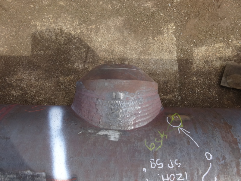
Could this be right (see photo attached)??

Generally speaking, which standard specifies how the weldolet branch connections shall be fitted? I mean when it's set it, set on etc. and what's the proper orientation (meaning which side goes onto run pipe)?

Thanks in advance for all kinds of feedback

JT
 
 http://files.engineering.com/getfile.aspx?folder=04e915b0-162f-487d-a8ca-ba3e271441d3&file=Weldolet_Plock.JPG
Replies continue below

Recommended for you

O'lets similar to that are typically set-on, don't think I've ever seen that style set-in.

Are there any markings left on the o'let? That's a clue to which end should be set on the run pipe.
 
That does look to me like a butt weld-o-let. However, its bevel has not been fully filled out with weld, which is required to develop the full pressure rating of the component as a self-reinforcing branch. If the full rating of the branch is not required (often the case, since the typical butt weld-o-let is 3000#), you will have to determine if the quantity of weld deposited is suitable for the service.

No idea why the welding looks so terrible- there's no scale to indicate how big this thing is...

It is possible that the o-let was set on with an excessive root gap between the end of the bevel of the o-let and the OD of the pipe. No idea why that would have been done.
 
The WOL in the picture can only be installed as a "set on" type of fit up. The part of the fitting that goes on the header is contoured to fit the contour of the pipe it's being installed on. Root opening tolerances are in welding procedure specifications. In all my years in the welding industry, I have never seen this type of fitting used with a "set in" type of fit up.
 
There is no "standard" per se. Bonney forge provide this as guidance
That thing looks more like a buttweld pipet, see
Looks horrible but might be OK if it's welded to the weld line.

The branch connection should be flat and the connection to the pipe contoured to match the OD of the pipe ( within certain ranges, e.g. 8" to 12" might be the same fitting)


Remember - More details = better answers
Also: If you get a response it's polite to respond to it.
 
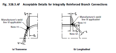
The current B31.3 edition, 2014, holds a pi ture on how to install/fit a weldolet.
 
Fig 328.5.4F no less. Learnt something today.

E
b31.3_branch_fitting_bta3mo.png
xample is

Remember - More details = better answers
Also: If you get a response it's polite to respond to it.
 
Weldolets and their Chinese clones are configured to match-up with a certain size of pipe ......one weldolet size does not work everywhere.

Compare the configuration of a 2" set-on weldolet configuration for a 4" NPS pipe versus one for a 20" pipe.

The weldolet in the picture is not the right size for the run pipe ...

Plus, the welder is an idiot ....


MJCronin
Sr. Process Engineer
 
Cut it off, refit and reweld it.

Before it becomes a projectile attached to one end of a pipe.
 
MJCronin - Could well be that this is a serious mismatch of fitting size versus actual pipe size.

QCJT- We could do with some feedback ourselves on the posts and information provided and what the outcome is.

Remember - More details = better answers
Also: If you get a response it's polite to respond to it.
 
Gent's sorry for not reacting to your valuable feedback so long. Due to unknown to me reasons the notification emails were ending up in the junk folder, so I didn't see any feedback till today... This is first time this happens, normally I get it all in my inbox.
Thank you all for practical tips and good answers (with sense of humor too). It's a pity that I can't update you on this matter, since nobody took any action on this piece and it seems it will stay as it is on the pipe, which is now on its way from pre-fab shop to the erection yard. I will advise our construction of course, based on your tips and will let you know what decision was finally taken!

Thank you very much.
JT
 
I hope that this doesn't fail when it's put into service, but that really looks dangerous and incorrect to me. Did it pass hydrotest?
 
Hi gwalkerb,

It hasn't been hydrotested yet and I do not think that the hydrotest will be a problem.

Best regards,
JT
 
Probably not a problem on hydrotest, only that the fitting doesn't meet the design code requirements and if it fails in service it will be your (you or your company) fault??

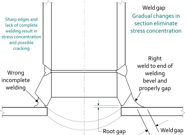
Looking at this again, whilst there might be a manufacturers weld line hidden below the top line of the weld, the concave nature of the weld is not permitted. This should be straight down as per the drawing in B 31.3. Otherwise you don't have enough metal for the area replacement design.

I don't think we've ever understood the branch and header sizes involved here, the wall thickness, the pressures, the contents or the design code (b31.3?) Also what is the branch? Does it have high vibration or stresses?

It still think that in the diagram below you are in the incomplete welding. Then compare your picture with the completed on below - compare and contrast.... If you saw an incomplete butt weld as shown on the diagram would you just let it go as well??

Does it need a lot of welding - yes it does.

weldolet_weld_detail_pyza0u.gif


weldolet_g2ijuq.jpg


Remember - More details = better answers
Also: If you get a response it's polite to respond to it.
 
Hi LittleInch,

Thank you for the post. Good one! However in our case I think the weldolet was installed upside down and without the due machining. My recommendation was to redo it and I'm trying to get the info now as to what has actually happenned...

JT
 
"I think the weldolet was installed upside down"

Meaning that nobody noticed the curvature on one end of the 'olet? Or that maybe it's actually a 'Flat-o-let'?
 
QCJT,
There have been a lot of "opinions" thrown out there but you know the old story - opinions are like ass.....!
You have an "integrally reinforced fitting" ( As per B31.3) and the only requirement is the material and weld metal thicknesses meet codes requirements and the weld is complete penetration.
Prior to posting this question did you actually look inside to check the root penetration or lack of ?
If the root is completely fused and there is sufficient weld metal (as per code requirements) - who cares if it is an ugly fitting made from recycled baked bean cans cast in a foundry somewhere in the upper Himalayas (sorry, always wanted to slip that one in)
Cheers,
DD
 
Gator,

This was picked up upon periodic visit to the shop and now it has been welded in proper way (see photo)

DSC04107_ts5sjg.jpg


Thank you guys for the feedback
 
Great. Thanks for the updates and good to know it has all worked out as it should.

LI

Remember - More details = better answers
Also: If you get a response it's polite to respond to it.
 
Thanks for posting the resolution, which makes all of us happier- and likely, also makes the end user of that piping safer too.
 
Status
Not open for further replies.

Part and Inventory Search

Sponsor