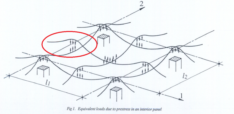
How the tendon profile is calculated for banded-distributed disposition? In the following figure why is the tendons profile one in the top fiber and the second in the bottom fiber? If the location is at the middle of the slab why do we place them opposite to each other doesn't that cancel the effect of the lower tendon?
Navigation
Install the app
How to install the app on iOS
Follow along with the video below to see how to install our site as a web app on your home screen.
Note: This feature may not be available in some browsers.
More options
Style variation
-
Congratulations cowski on being selected by the Eng-Tips community for having the most helpful posts in the forums last week. Way to Go!
You are using an out of date browser. It may not display this or other websites correctly.
You should upgrade or use an alternative browser.
You should upgrade or use an alternative browser.
What are the general consideration for tendon profile in a post tension slab? 4
- Thread starter JDG3718
- Start date
- Status
- Not open for further replies.
One of the important goals of tendon profiling is load balancing. The idea with load balancing is essentially to laterally move loads applied to the slab over to the columns without involving the slab concrete in bending or shear. Where you have sagging curvature, you're picking up gravity loads; where you have hogging curvature, you're depositing gravity loads.
They would tend to cancel. In a banded/distributed system I'd expect the mid-slab strands runnning parallel to the bands to run fairly straight. Profiling them as shown in your photo would tend to counter the one-way behavior that you're usually trying to encourage in the distributed direction. It may result in undesirable cracking in the distributed direction column strip if some additional tendons are not placed there, creating a version of a dual banded system.
I like to debate structural engineering theory -- a lot. If I challenge you on something, know that I'm doing so because I respect your opinion enough to either change it or adopt it.
JDG3718 said:If the location is at the middle of the slab why do we place them opposite to each other doesn't that cancel the effect of the lower tendon?
They would tend to cancel. In a banded/distributed system I'd expect the mid-slab strands runnning parallel to the bands to run fairly straight. Profiling them as shown in your photo would tend to counter the one-way behavior that you're usually trying to encourage in the distributed direction. It may result in undesirable cracking in the distributed direction column strip if some additional tendons are not placed there, creating a version of a dual banded system.
I like to debate structural engineering theory -- a lot. If I challenge you on something, know that I'm doing so because I respect your opinion enough to either change it or adopt it.
- Thread starter
- #3
-
1
- #4
Try this for starters: Link
I'd recommend scouring the PTI and VSL websites for resources. They've both got all kinds of good stuff available for free.
If you're getting seriously into unbonded PT in the North American market, I'd recommend procuring a copy of this: Link
I like to debate structural engineering theory -- a lot. If I challenge you on something, know that I'm doing so because I respect your opinion enough to either change it or adopt it.
- Thread starter
- #6
-
1
- #7
If the circled area represents a distributed tendon depositing load on a banded tendon group, then that makes sense to me. It's somewhat analogous to a beam depositing load on a girder.
On the other hand, if it's a distributed tendon depositing load on another distributed tendon, then I question the efficacy of the scheme. This document shed some insight on the performance of the various layout schemes. You may find it of interest.
Can I ask where the sketch that you posted comes from?
I like to debate structural engineering theory -- a lot. If I challenge you on something, know that I'm doing so because I respect your opinion enough to either change it or adopt it.
That diagram is totally consistent consistent with KootK's description of using the tendons to move the vertical loads laterally.[ ] The loading in the middle of the panel is moved (bi-directionally) to the middle of the "column strips", then it is further moved to the actual column.
- Thread starter
- #9
the picture is from the attached document , thanks for the help guys.
You're most welcome. And thank you for the reference. No doubt, the sketch above accurately represents the lateral movement of load in a pre-stressed floor system. The only question is the kind of performance that can be expected in such a system. The paper that you posted gives consideration to systems that certainly would perform well with such a layout (waffle slabs with two way solid bands etc).
I like to debate structural engineering theory -- a lot. If I challenge you on something, know that I'm doing so because I respect your opinion enough to either change it or adopt it.
I like to debate structural engineering theory -- a lot. If I challenge you on something, know that I'm doing so because I respect your opinion enough to either change it or adopt it.
- Thread starter
- #11
maybe I am missing something but is the jacking stress taken 0.8fpu (fpu is the ultimate stress in the strand) ? because in the field when the jacking process is done the worker was looking at the gauge and stoped at 5300 PSI and that was weird because 0.8*270000 = 216000 PSI and that is way higher the jacking stress in the field can anyone clarify how is jacking stress calculated ?
-
1
- #12
JDG3718 said:maybe I am missing something
You are mixing up hydraulic pressure of the stressing system with ultimate tensile strength of the strand.
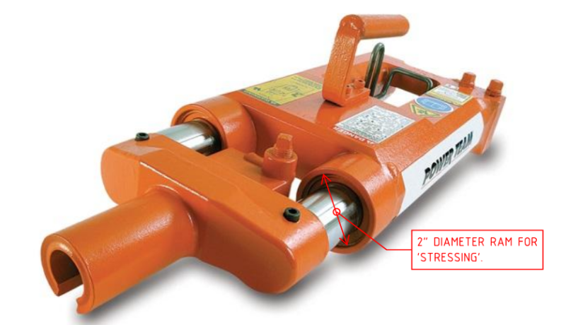
5300 psi gauge pressure is the hydraulic pressure in the pump/jack system used to stress the tendon. 5300 psi corresponds to a effective ram area of the jack of 6.28 in2 (ie 2 rams of 2" Ø = 6.28 in2). 6.28 in2 x 5300 psi = 33 kips. Technically, the 5300 psi is arrived at from the current calibration certificate that gets undertaken very 6 or 12 months of the gauge/pump/jack system.
33 kips is 80% of MUTS of a 1/2" Ø 7-wire strand. Ap = 0.153 in2 so 80% x 270 ksi x 0.153 in2 = 33 kips.
EDIT: Photo to describe the effective ram area:

-
1
- #13
JDG3718
What you have shown is not a banded distributed layout. Banded/distributed is banded in one direction and equal spaced in the other, like a one way beam and slab (without the beam). This is a PTI/ACI invention for flat slabs that requires special rules for calculations for strength, minimum reinforcement and crack control and deflection calculation as the tendon arrangement bears no relationship to the moment/stress distribution in the slab.
You have shown a two way layout, with middle strips in each direction carrying the load to column strips in each direction. This basically results in banded strips in both directions and is similar to the arrangement of the bending moments in the slab . A good way to think of this arrangement is
- equal spaced tendons in each direction carry 50% of the slab load in each direction to the support lines.
- Bands of tendons on the support lines in each direction then carry the reaction from the equal spaced tendons to the supports.
An Ingenuity pointed out, gauge pressure is not strand load. There should be a calibration for the gauge that equates gauge pressure to strand force/stress.
- Thread starter
- #14
rapt said:A good way to think of this arrangement is
- equal spaced tendons in each direction carry 50% of the slab load in each direction to the support lines.
- Bands of tendons on the support lines in each direction then carry the reaction from the equal spaced tendons to the supports.
Therefore, 100% of the applied loads are carried in EACH direction for 2-way slabs supported on columns.
Ingenuity
Your Math is improving!
The 50% each way logic for the distributed tendons can actually be varied, especially where the longitudinal and transverse span lengths are very different. And then the banded percentages change accordingly to still give a total of 100% in each direction. In this 2way logic, this variation should be consistent with the way the elastic moment distribution would vary in the slab.
The one way banded distributed logic is a variation on this where the distributed tendons carry 100% in one direction to the support line, and then the band in the other direction carries this 100% to the supports, but the relative distributions in the 2 directions are not related to the elastic moment distributions in the slab. So very large redistribution of the elastic moments in the slab is required to get the moments into the same pattern as the tendon pattern. This can cause serviceability (increased cracking and deflection) problems if the redistribution happens under service loading conditions and requires that the slab be sufficiently ductile for the redistribution to happen at ultimate strength.
That is why the special rules on minimum reinforcement, etc that I mentioned above are necessary. And also part of the reason, along with the need to design based on average panel moments and strength, why the methodology does not work properly for slabs with drop panels.
rapt said:Your Math is improving!
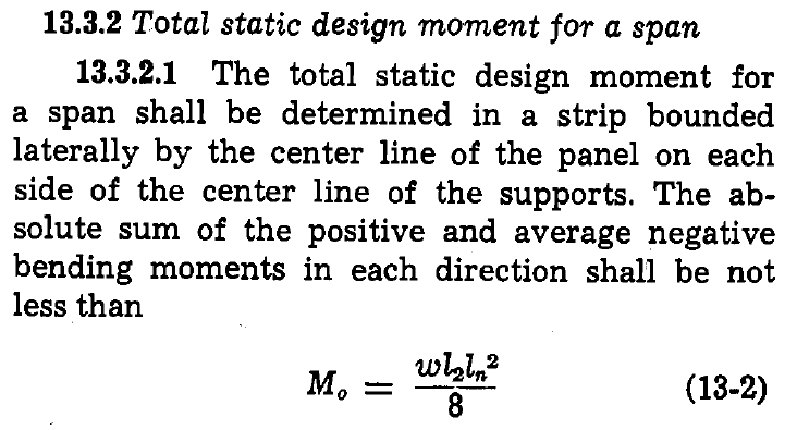
I mentioned this because it was not too long ago that ACI 318 permitted engineers to design 2-way column-supported slabs for 80% of statics for flexure. Changed in 1971, I think.
rapt said:80% was an improvement compared to what they did in the first half of the 1900's!!
I was partially correct, bit out on my date and %:
From ACI 318-1963:

From ACI 318-1971:

So prior to 1971 is was 72% (not 80%) of statics.
In the early 1900's C.A.P Turner (and professors like Eddy from U of Minnesota) were using co-coefficient as small as 1/50 (cf 1/8!!!) for flat slab systems.
It was J.R. Nichols work/paper that eventually prevailed.
- Status
- Not open for further replies.
Similar threads
- Replies
- 2
- Views
- 2K
- Locked
- Solved
- Replies
- 1
- Views
- 1K
- Question
- Replies
- 22
- Views
- 17K
- Locked
- Question
- Replies
- 4
- Views
- 2K
- Replies
- 22
- Views
- 3K


![[thumbsup2] [thumbsup2] [thumbsup2]](/data/assets/smilies/thumbsup2.gif)