Continue to Site

Eng-Tips is the largest engineering community on the Internet

Intelligent Work Forums for Engineering Professionals

  • Congratulations SSS148 on being selected by the Eng-Tips community for having the most helpful posts in the forums last week. Way to Go!

What bearing possibilities?

Status
Not open for further replies.

BrowserUk

Student
Jul 14, 2022
21
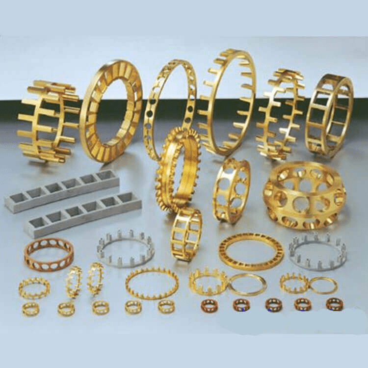
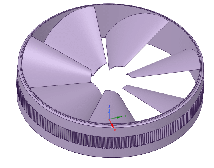
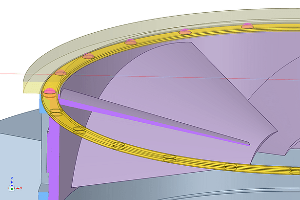
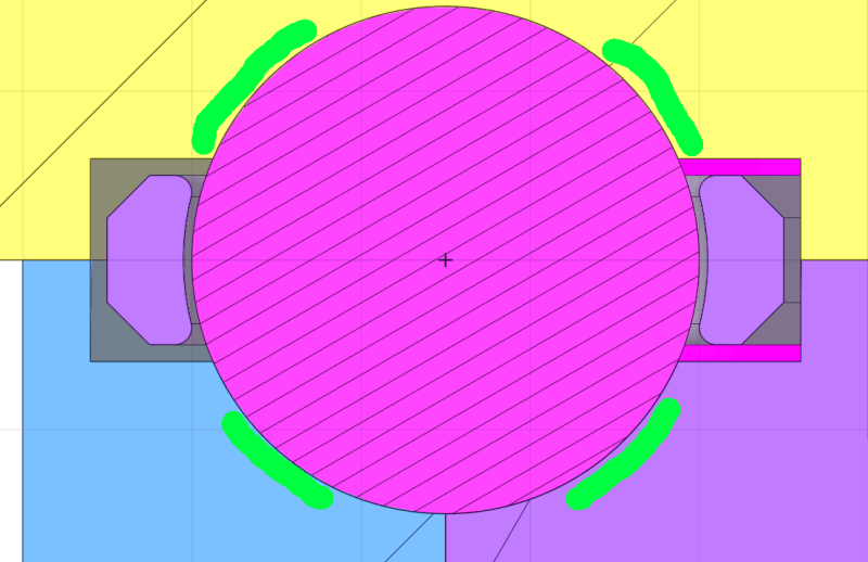
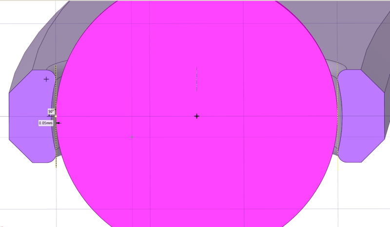
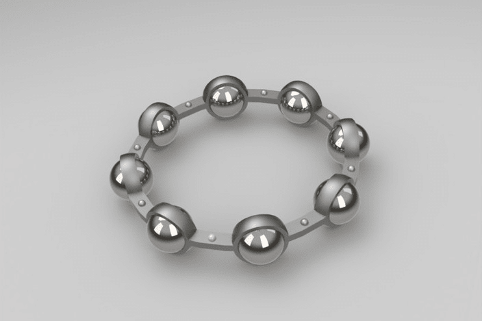
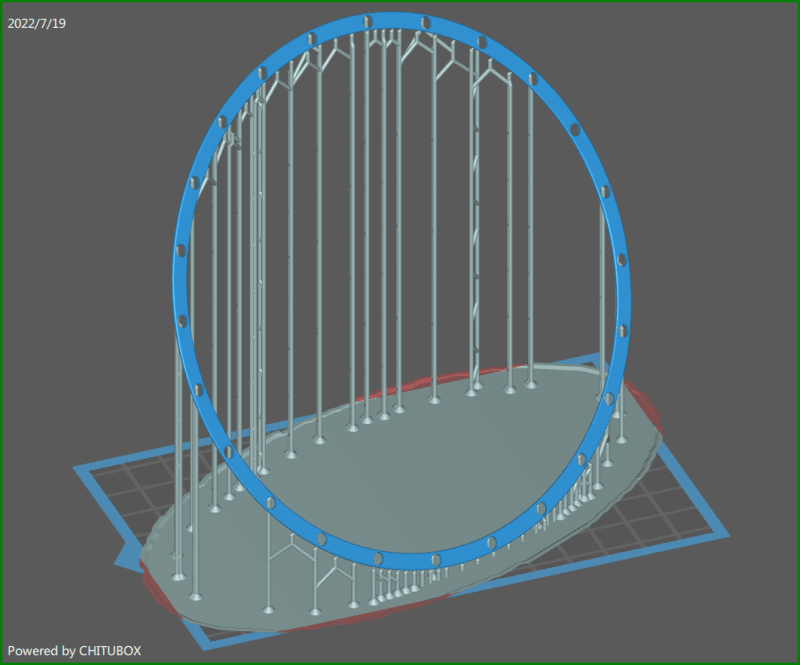
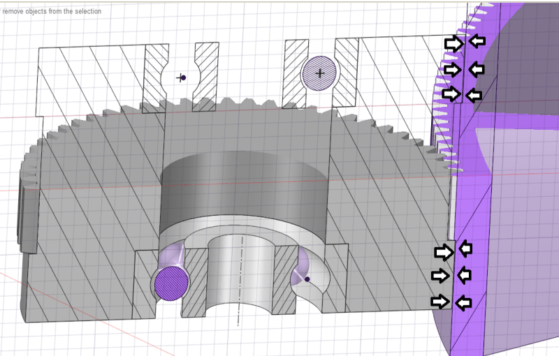
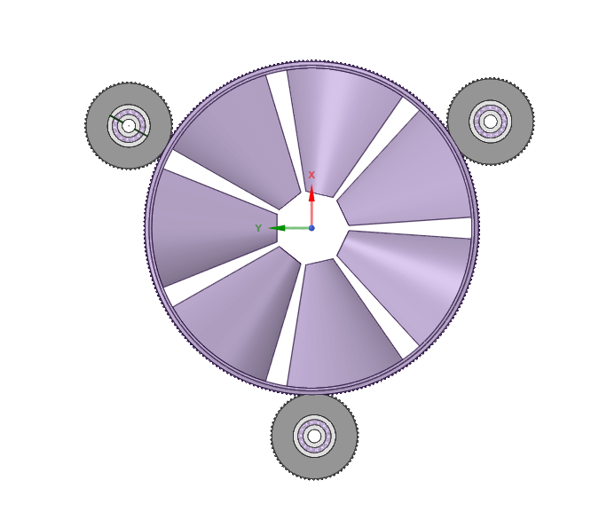
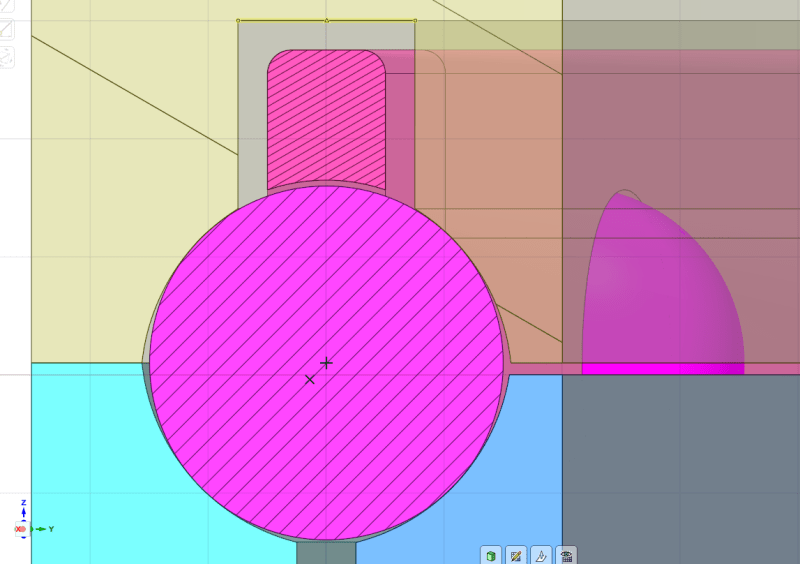
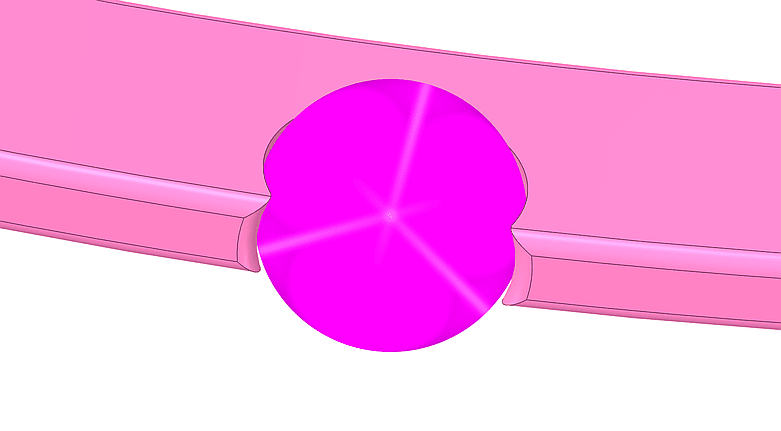
What methods are possible for "bearings" for a 120mm diameter x 50mm rim-driven, HUBLESS rotor?

Mass: ~128.5g
RPM: 2000-3000
Forces:
Radial: its own (well-balanced) mass x angular velocity.
Axial: ~500g in one direction.

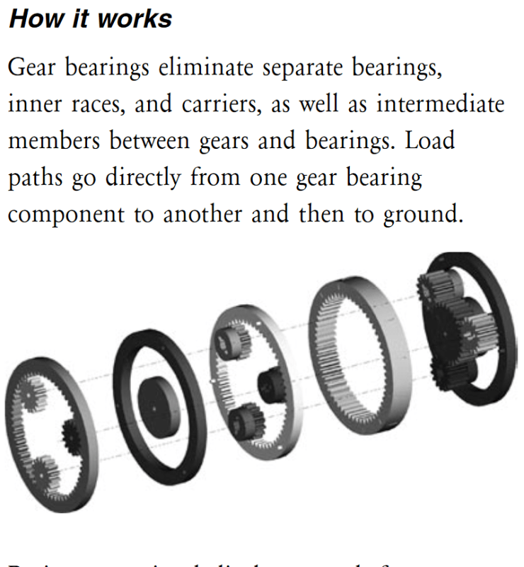
Note: Besides the ludicrous costs, stuff like this is excluded because of weight.

Looking for ideas, possibilities...
 
Replies continue below

Recommended for you

3DDave:""How fast will THOSE be rotating?"

Sorry, misunderstood you.

As drawn, the gear ratio is 7.5:1, so the 5x16x5 bearings would be doing circa 20,000 rpm.

As open bearings they are good to 43000rpm; or 36000 with seals.
 
3DdDave:"There's not a lot of extra friction from spacers, which is why they are used. "

The problem with a traditional cage spacing arrangement,
junk_t3nux0.png

is where do you put it?

Purple is the rotor; blue the body in which it rotates, yellow the flange that retains the upper bearings:

junk_ezo2vd.png


An alternative possibility is to use 'rod' spacers something like this:
junk_cfioo5.png


Hollow to cut down inertial mass; smaller diameter than the balls tro prevent rubbing in the race;
ends shaped to be a close fit to the balls so that they 'float'.

Problem is that the tolorance between too tight--can't move and too loose--rubs everywhere is very small:
junk_hc5b9u.png


And they are a pain in the butt to print.
 
BrowserUK said:
is where do you put it?

Welcome to designing things. Of all the problems you've asked questions about this is probably the easiest one.

Hint: individual spacers is the wrong path.
 
SwinnyGG: "Welcome to designing things. Of all the problems you've asked questions about this is probably the easiest one."

So easy you've decided to keep the answer -- to the ONLY question I have asked -- as an exercise for the reader. Thanks a bunch.
 
The point of this forum is not for you to come here and ask a question and we do your homework for you.

You know exactly what you have to do - you need to make space in your assembly for a bearing cage. You don't want to, because of some constraints you don't want to tell us about.

For the third time - the more detail you provide, the better your answers will be.
 
I'm a 65 y/o with 45+ years of engineering experience taking remote study courses for my own edification.
I could only register here as a "student"; as I do not have a 'company name' to satisfy any other category.
(I almost never did; I was a self employed consultant for the last 34 years of my career.)

This is not "homework" in the sense you mean. (I'm doing it at home; but I do not consider it work.)

I came looking for some creative suggestions from experts, based upon their experience; instead I get the guesswork of jumped up, self-important wannabes.

They'll ban me for speaking my mind; but ce la vie. I'll learn nothing useful here anyway.
 
They won't ban you unless someone complains. Which won't be me, you're entitled to your opinion.

We can't provide creative suggestions to vague questions where we don't know what the constraints are. So, for the fourth time: the more information you provide about what you're trying to accomplish, the better (ie... creative and potentially more helpful) responses you're going to get.
 
If you have yet to understand the question, why suggest you have an "easy answer" and then withhold even a hint to it.
No one asked for fully worked solutions; just ideas.

Which I will once again summarise as: How to support this rotor (~128.5g), whilst it spins on its own axis at 2000-3000 rpm, generating ~500g of thrust
without using a central axle:
junk_xagi5c.png


No other information is required to describe the problem; nor to identify solutions.
And all of that was identified in the OP.
 
BrowserUK said:
No other information is required to describe the problem; nor to identify solutions.
And all of that was identified in the OP.

Your own posts have highlighted cost and weight concerns which are apparently constraints on your design decisions, which you haven't told us anything about.

You already have a design roughed out with a couple of paths to a solution. The one thing you need, as far as I can tell, is a solution to the problem of integrating a bearing cage into your edge-located thrust bearing. This is not really a difficult thing to do. One of your parts has to grow, sufficient that it has enough material for an internal volume to accommodate a bearing cage. That's it. If you have as much experience as you claim to have, this is a trivial detail to work out. None of us are going to spend an hour working up a detail in CAD for you, especially when you're hostile toward people trying to tease information out of you so they can help you.

Your concept for providing drive power has problems of its own, but you've made it abundantly clear that you came here for us to solve this one problem for you, and don't want feedback on anything else. So, I'll keep my thoughts to myself.
 
SwinnyGG: "None of us are going to spend an hour working up a detail in CAD for you,"

Why would you think that I would need you to do that? Have I not shown myself perfectly able to produce my own CAD in response to eevry question?

SwinnyGG: "The one thing you need, as far as I can tell, is a solution to the problem of integrating a bearing cage into your edge-located thrust bearing. This is not really a difficult thing to do. One of your parts has to grow, sufficient that it has enough material for an internal volume to accommodate a bearing cage. "

I assume you mean something like this:
junk_zjwx8l.png


Let's look at that idea in detail:
junk_gzbulc.png


In order to support the load both radially and axially, it will be necessary to retain material in the raceways at diagonally opposed areas as highlighted in green above.

And that places an upper limit on the thickness of the cage, so it ends up looking something like this:

junk_fbuhrw.png


Can you see the problem yet?

If you make the clearance sufficient to prevent high friction in use, the hole is too big to retain the balls.
0.05mm (a gnat's under 2 thou if you are of that persuasion). I cannot 3D print any tighter.
And if I could, how would I get the balls in to the cage?

I guess if I had the equipement at home to produce a 2-part, pressed phosphor-bronze cage and rivet them together something like
junk_pti2dd.png


I might be able to make it work; but I have to live in the real world where 3D printing a 1mm thick, 4mm wide, 120mm diameter ring like this fraught with problems:
screenShot_120m_bearing_cage_zdyk8t.png


Even if I could make the hole tolerences tight enough to retain the balls, the idea that I would be able to get something as large, thin and delicate as that to print correctly is inconceivable.
 
SwinnyGG: "Your concept for providing drive power has problems of its own, but you've made it abundantly clear that you came here for us to solve this one problem for you, and don't want feedback on anything else. So, I'll keep my thoughts to myself. "

No need to be coy!

First off. If the gear bearings solution was a complete solution, I wouldn't be here looking for alternatives.

Before you go off half cocked though, take a look at this NASA licencing page for their patent for "Gear bearings".

An extract:
junk_mkscof.png


Know that these have been implemented in many satellite's -- some you might have heard of; many you will not have -- reaction control mechanisms.

I know, because I designed some of them.
 
Yep. That was pretty easy, no?

You can likely get away with a wider cage than that; I'd start with a cage width of roughly half the ball diameter. Remember that your radial bearing forces, assuming your rotor is well balanced, are going to be pretty low.

You don't need the cage to retain the balls; you need the cage to keep the balls evenly spaced. That's it. Can't 3d print it? Buy a sheet of 1mm PTFE and cut it by hand. There's solutions out there. Everything in the world cannot be 3d printed.

You could also turn the whole arrangement 90 degrees, if it makes it easier for you to package. You're approaching Greg's original proposal of building the inner bearing race into the rotor at that point. That's do-able as long as this thing doesn't have to last forever. I think we're all assuming this is a prototype.
 
SwinnyGG:"Yep. That was pretty easy, no?"

I guess you only read half of the post to which you responded. (My bad! I hit post instead of preview before it was complete.)

Please re-read it and see why it doesn't work unless you have production facilities.
 
I'll say it again.. you don't need the bearing cage to retain the balls. All it has to do is keep them evenly spaced. It can be very thin, although it doesn't need to be. It also doesn't need to be 3d printed. Buy some PTFE sheet and an xacto knife and with some careful work you have a prototype bearing cage in about an hour, maybe.

I'm aware of the existence of gear bearings.. what you've proposed isn't really a gear bearing. Ultimately I think you're going to have problems if you're using the gear teeth for radial location and transmitting power at the same time; your teeth are too small to have good profile control at your best print resolution, and even if they are well profiled, adding a bunch of radial tension to the interfaces is going to cause the gear teeth to eat themselves in short order. But hey, maybe not. We don't really know if that's a problem or not, because we don't know how long you intend for this unexplained gadget to last at 3,000 rpm.
 
SwinneyGG: " Ultimately I think you're going to have problems if you're using the gear teeth for radial location and transmitting power at the same time;"

That doesn't happen. The rotor is located radially by the bearing surfaces above and below the gearteeth (as arrowed in this two-plane cross-sectional view):
junk_vspebj.png


which ensures that the teeth do not become wedged into each other.

Three of these gear bearings at 120° provide 6 points of radial location:
junk_x0ozjw.png


Two of these are undriven, and the teeth only serve to ensure a non-slip operation.
 
Fair enough. Do you know you're going to maintain the gear tooth relationships under full power? With the perimeter shell being thin, I was thinking warping of that shell might be an issue.
 
SwinnyGG: "you don't need the bearing cage to retain the balls. All it has to do is keep them evenly spaced."

If the cage is not centred by the balls, then in addition to the friction from the small areas of contact between balls within the cage holes;
you also have full circumference drag between the face of the cage and the raceway.

SwinnyGG: "Buy some PTFE sheet and an xacto knife and with some careful work you have a prototype bearing cage in about an hour, maybe."

Have you heard of PTFE creep?

Within minutes of operation, the holes will elongate, the edges of the holes in the direction of rotation will be skwished down to form ramps, and the balls will ride up and the whole kit & kaboodle (industry term) will jam.

There are filled-PTFE (Glass fiber; Molybdenum DiSulfide) alternatives that resist creep, but trying buying sheets of it! (And you wouldn't be engineering that with an Xacto knife.)

And other polymers that might serve teh purpose, but they would need proper engineering and I don't have that capability.

 
SwinnyGG:" Do you know you're going to maintain the gear tooth relationships under full power? With the perimeter shell being thin, I was thinking warping of that shell might be an issue."

Everything is a trade-off. I can increase the thickness of the rim to allow the use of bigger teeth, but that increases the rotational mass, which increases the startup torque requirement.

The blades are moving (a lot) of air; but it's only air. Lift and drag increase with the square of the speed, so at startup, there is little resistance.

The torque requirement builds slowly and progressively. If I need to limit the rate of acceleration, that quite doable.
 
SwinnyGG: "You could also turn the whole arrangement 90 degrees, if it makes it easier for you to package."

I kept dismissing this on the basis that it created more problems than it solved -- and it does if I distribute the cage equally around the balls -- but the notion struck that I don't have to do that.

junk_dgu7yo.png


By distributing the cage asymmetrically around the balls, it should give me enough flexibility to snap the balls into place and make them 'captive' without requiring them to be a tight fit;
and by arranging the cage vertically to sit on top of the balls, it will ride on top without touching the races; even if I cannot make the balls actually captive.

junk_gvevqc.png


Further, I can split the cage into 3 or more pieces and print them flat on the bed of the printer:

screenShot_120mm_vertical_bearing_cage__split_3_pt9x7e.png


So thank you for persisting!
 
Status
Not open for further replies.

Part and Inventory Search

Sponsor