Eng-Tips is the largest engineering community on the Internet

Intelligent Work Forums for Engineering Professionals

What determains the steaty-state velocity of an open loop DC motor?

Status
Not open for further replies.

David Ren

Student
Mar 22, 2024
5
0
0
IL
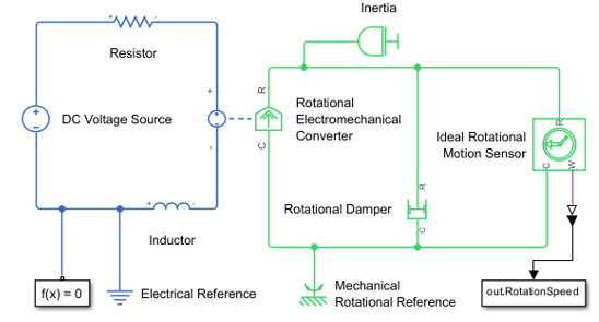
I have a Simulink model of an open-loop DC motor.
I am trying to understand what parameters effect the final steady state angular velocity of the motor.
From playing around with different values, it seems that:
A. The input voltage, electric resistance, viscous resistance (damper) and torque constant have an effect on the steady state velocity
B. The Inertia and electric inductance do not affect the final speed, but rather only effect the time it takes to reach this speed.

Am I correct? Why is this? my intuition says that also the inertia should influence the steady state speed, but it seems my intuition is wrong.
Thanks!


model_ss95va.png
 
Replies continue below

Recommended for you

Two things to think about:

1. Why does your intuition say that inertia should influence steady state speed? (Don't try to answer that - who can explain intuition). If the problem was linear and there was no electricity involved (say you were seeing how fast you and a friend could push a wagon along a level rail track), would you still expect inertia to govern ultimate speed?

2. How confident are you that your model is complete? Have you come across the concept of "Back EMF" yet? This is a really significant factor in the steady state speed of dc motors.

A.
 
Putting intuition aside, since inertia is the tendency of an object to resist change in its motion, it would imply that the higher the inertia the more the motor would resist the increase in speed. how does this not lower the final speed?
Imagining the wagon setup you described, yes, i would have that same expectation. You say that there as well, the ultimate speed would not be dependent on the inertia of the wagon?

The model was taken from a tutorial I saw a while ago, I couldn't find it right now. I am pretty sure it is correct, yet I am sure it is not 'complete', since there are probably many more effects in real life...
 
You're confusing transient effects with steady state.

The inertia affects the transient state, i.e. how long does it take to get to full speed.

It has no impact on the final steady state, which could arrive in 0.1 sec, 1 second, 1 minute, 1 hour depending on the amount of inertia. But the end result will be the same once it stops accelerating.

Remember - More details = better answers
Also: If you get a response it's polite to respond to it.
 
I chose the wagon experiment because it's a good example of a high mass, low friction system which comes relatively close to obeying Newton's laws. Those laws say that, for as long as you keep pushing, the wagon will keep accelerating. The mass of the wagon (inertia) governs how much acceleration you get for your force (and hence how long it takes the wagon to reach any particular speed). What actually governs the final speed of the wagon is how fast you can run - if you can't keep up with the wagon, you can't keep pushing it - and that doesn't depend at all on the inertia of anything.

The no-load speed of a dc motor is a similar story. As speed increases, electromagnetic effects (Back EMF again) reduce the torque generated by the windings until you reach a speed where the motor stops generating torque altogether.

I think that behaviour is already baked into the Simulink dc motor block so, when you specify the torque constant, you are also specifying the no-load speed (per volt). There are real-world strategies for trading torque for speed (look up field weakening for example), so it's a legitimate parameter to alter as part of your investigation.

A.
 
Let's examine a DC machine.
The same machine may be a generator or motor depending on the application.
For this discussion and for understanding assume that this is a test machine connected to a dyno and that the field and armature voltages may be controlled or varied.
The dyno may control the speed and is capable of overcoming the motor torque or supplying the generator torque.
To start, apply rated field voltage and rated current and no load from the dyno.
The motor will stabilize at no-load speed.
Now over-drive the machine with the dyno until the armature current is zero.
The back EMF now matches the applied voltage, no armature current flows, no torque is developed and the machine is neither a motor nor a generator, but it is still a DC machine.
Now drop the speed a little below the neutral speed;
The back EMF drops and current starts to flow in the armature circuit. The dyno is acting as the load and as increased load slows the motor, the back EMF continues to drop and the armature current continues to increase.​
Now increase the speed a little above the neutral speed;
The back EMF increases and current starts to flow in the armature circuit. The dyno is acting as the prime mover and as increased torque speeds the motor, the back EMF continues to rise and the armature current continues to increase, but in the opposite direction.​
Now, rather than holding the applied voltage constant we will hold the speed constant and vary the applied voltage.
Lower the applied voltage below the back EMF and our machine becomes a generator. The armature current will increase as the voltage is dropped and the torque exerted by the dyno to maintain the speed will increase.​

Increase the applied voltage above the back EMF and our machine becomes a motor. The armature current will increase as the voltage is increased and the torque exerted by the motor on the dyno will increase.​

In a well designed, efficient DC machine, held at constant speed, there is only a few volts between motoring and generating.

In a well designed, efficient DC machine, with constant voltage applied, there is only a few RPM between motoring and generating.

If you understand DC motor basics, you should be able to discern what will happen when the voltage and speed of a DC machine are both held constant but the field strength is varied.
I leave it to you to work that out.
ps; I'm old and tired so beware of typos.

--------------------
Ohm's law
Not just a good idea;
It's the LAW!
 
And did I mention that the armature current is driven through the effective resistance of the armature circuit by the DIFFERENCE BETWEEN the APPLIED VOLTAGE and the BACK EMF.

--------------------
Ohm's law
Not just a good idea;
It's the LAW!
 
Status
Not open for further replies.
Back
Top