Continue to Site

Eng-Tips is the largest engineering community on the Internet

Intelligent Work Forums for Engineering Professionals

  • Congratulations KootK on being selected by the Eng-Tips community for having the most helpful posts in the forums last week. Way to Go!

What happens when two sources are paralleled into one bus and the 15kV voltages are off by 400V ? 4

Status
Not open for further replies.

bdn2004

Electrical
Jan 27, 2007
792
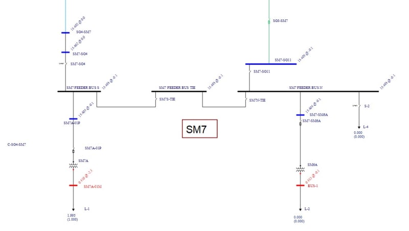
We are trying to do a hot switchover of this 15kV bus that is fed from two different sources. I've tried to model it with EasyPower software.
According to the software there is a 400V difference between the one system and the other. Is there a problem doing this?

SM7_Tie_nc05nq.jpg
 
Replies continue below

Recommended for you

It depends.

What's the cause of the 400V difference? Is it due to a turns ratio mismatch between the mythical infinite bus and this location or is it due to load driven difference in voltage drop across different parts of the system?

When you tie them in the model, what happens? Does the resulting voltage match, or at least be close to, one of the initial conditions or does it wind up somewhere in between? What's the standing current flow between the sources when you close the switch?

When one this sentence into the German to translate wanted, would one the fact exploit, that the word order and the punctuation already with the German conventions agree.

-- Douglas Hofstadter, Jan 1982
 
The higher voltage source will supply a greater share of the reactive power.
400V/15000V x 100 = 2.67%
With one source loaded and one source unloaded (at the point of common coupling) I am not surprised that there is a small voltage difference.
Remember that energizing a dead bus, the voltage difference is 15 kV.
Once you close in, the load will be shared in inverse proportion to the source impedances.
VAR sharing is influenced by the voltages.
After the transfer, the bus voltage may be higher or lower than the original voltage.
With the incoming voltage higher than the existing voltage, the voltage after transfer may be higher or lower than the original voltage.
It depends.

ps; Consider two identical transformers on different taps.
VAR sharing is more affected than load sharing.

--------------------
Ohm's law
Not just a good idea;
It's the LAW!
 
Oops.... The Client had guestimated 200V of voltage drop to where this hot switchover is located in the Plant. There is no metering at that point to confirm it.
Thus why we are trying to model it. But I input the data wrong on the original above. He told me the transformer tap is set to 4R which equated to 141.54 kV and the secondary voltage is measured at 15.40 for Utility 1. Utility 2 is metered at 15.40 kV. So it's more like 3 Volts per the software. Another issue of concern is the Capacitor Banks at Utility 1 being connected which adds to the voltage, so we still have the same question.

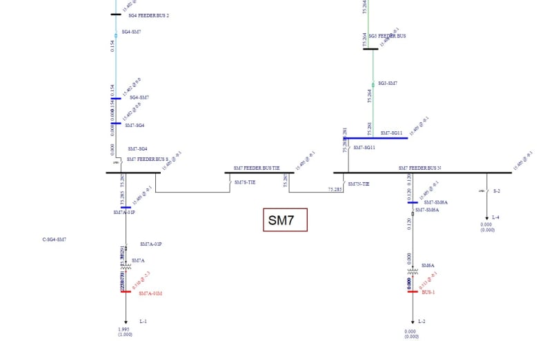
SM7_Revised_zci6r4.jpg
 
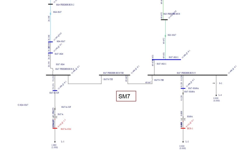
This the currents with only the Utility on the right feeding it. Below that is with the switch closed.

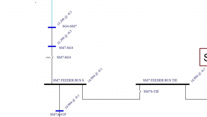
SM7_-_SG4_switch_open_bqtpac.jpg


SM7_-_SG4_switch_closed_upw263.jpg
 
the secondary voltage is measured at 15.40 for Utility 1. Utility 2 is metered at 15.40 kV.
With different loading on the two lines, different voltages at your site are not unusable.
During the short time that both breakers are closed, there may or may not be some current from one source passing back into the other source to reduce the voltage drop on that line.
If both source voltages are equal, there should be no problem paralleling the ends of the lines.


It's close enough. Just close the switch.


--------------------
Ohm's law
Not just a good idea;
It's the LAW!
 
Does EasyPower let you simulate what happens when both sources are closed?

A few things to check:
1) Does the utility permit the customer to parallel behind the meter? Some utilities require drop/pick for customers with dual feeds unless there are reverse power relays on both connections.
2) What is the magnitude of the circulating current cause any problems? It is pretty easy to estimate the circulating current by following steps in 3) Will the circulating current cause any problems like overloaded wires, flows above trip settings, or trips on reverse flow.

If I were paralleling two 115 kV/15 kV transformers in a substation, 400 volts would typically be excessive difference. If I were parallel two 15 kV circuits a kilometer outside a substation, 400 volts would be normal.
 
I did this kind of make-then-break switching for years, and I'm with Bill; 400VAC difference on a 15 kV [ for us it was 13.8 or 14.4 kV ] is notable, but not overly excessive.

What I always did though was to pre-calculate how much VAR change would occur once the switch was closed, then, once parallel had been made, adjust the taps on the sources so that the VARs across the switch to be opened were as close to zero as possible. Note that you will be adjusting flows you can see to achieve a derived result that you may not be directly able to meter.

There may be some off-normal voltages once parallel is broken, but these can be quickly remedied by adjusting source taps to suit the new conditions.

AHJs however may take a different tack on this; bacon4life posed the question of "Does the utility permit the customer to parallel behind the meter? Some utilities require drop/pick for customers with dual feeds unless there are reverse power relays on both connections," and it's a crucial one; you may be forced to go break-before-make, taking a partial load interruption in the process [ unless there's a generator in there to carry the isolated load . . . but I digress ].

CR

"As iron sharpens iron, so one person sharpens another." [Proverbs 27:17, NIV]
 
LTC controllers designed for parallel operation often have a trip limit set on how much circulate current they allow before locking out the tap changing function. A 400 volt difference is quite close to what would block the LTC controller from further action. If that occurs, it just requires someone to locally manually adjust taps and reset the controller.
 
The switching I touch on all took place "ahead of the meter" and thankfully no direct circulating current limiting trip of LTCs was installed anywhere that I ever encountered.

Where to locate the metering in the design stage is very important; anecdote follows.

A new 230 kV-connected power generating facility had its site metering installed in the pair of circuits connecting it to the grid. Upon completion of full commissioning it soon became apparent why this was a very, very bad idea: a major planned outage to some equipment on one of the said 230 kV circuits caused a large circulating current to flow through the closed ring bus for the site.

The result: even though all units were off line, the outflow on the one circuit leg was credited as production at the lower generation price, while the inflow on the other circuit was billed at the much, much higher consumption price. The power bill the site received for that first month defied description, and took many, many months of legal wrangling and analysis to sort out - and led to the site running with a split bus unless generating heavily.

CR

"As iron sharpens iron, so one person sharpens another." [Proverbs 27:17, NIV]
 
@bdn,
Don't overthink it. There will always be slight differences in voltages. Just let the synchronizer do the job. You won't get synchronized if the differences are too big for the control equipment.
 
Status
Not open for further replies.

Part and Inventory Search

Sponsor