Eng-Tips is the largest engineering community on the Internet

Intelligent Work Forums for Engineering Professionals

What is the best practice to 3D model and detail weldments that have sheet metals as a part of them.

Status
Not open for further replies.

Imposter666

Mechanical
Jan 15, 2021
36
0
0
CA
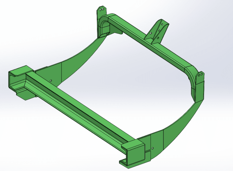
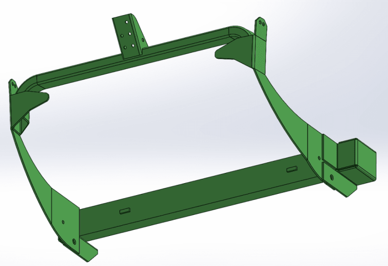
I have made plenty of structural weldment designs and detailing. The same goes for the sheet metal. However, it is my first time making weldment with medium to complex sheet-metal shapes welded onto the tubes. If I model the sheet metal as a body, how can I show the flattened view? Or is it better to make them separately and combine them in an assembly file? The latter seems counter-intuitive to me. What is the best way to handle this. I will have to model plenty of parts like this, and I would like to adopt the best practices.

Thank you!

Screenshot_2024-01-26_091735_emxz2t.png


Screenshot_2024-01-26_091701_ltde3m.png
 
Replies continue below

Recommended for you

Hi, Imposter666:

You can make a weldment with derived sheet metal parts. That will do what you are trying to do. You can have flat views for each part that are contained in your weldment.

I agree with Chris. Assembly modelling is a better approach as it has more flexibility.

Best regards,

Alex
 
Hi, Imposter666:

I never attempted to try to flatten a sheet metal body. My instinct tells me that you can't do it.

You can make those components as individual part file (*.sldprt) as sheet metal.

Then, you can bring those components into your next level weldment part (also *.sldprt). You can add weldment features as you need.

An assembly models are more efficient and are easier to be modified. But you can't have weldment features on the assembly model.

Best regards,

Alex
 
Never blend Weldments and sheet metal together. Make an assembly. Just because SW allows multi-bodies into one file doesn't mean you should blend those two types of features.

As for bending it and flattening it. It's good to be able to do that to add things to the sheet metal part. However unless you are doing the bending at your facility, only send the bent file/drawing to the vendor. They might ask for the flat DXF but I would stipulate that it's on them to find the location of the internal features. Each press is different and only the vendor knows what those numbers are. I worked for a shop that did its own sheet bending and though we asked for the DXF it was my job to figure out where the internal features are to be located and all the bend line locations.

Scott Baugh, CSWP [pc2]
Mechanical Engineer
Ciholas

"If it's not broke, Don't fix it!"
faq731-376
 
Hi Imposter666
Have you explored the View layout command called Relative View to treat the various bodies in a multi body part seperately?
Regards
DD24
 
I have done several SW weldments consisting of sheet metal parts. It can be done. One must be very careful and understand exactly what they are doing. If properly done each sheet metal body will also have its own flattened state. One becomes a master of configurations in the process because that is the key to showing individual weldment bodies in their flattened state in the relative views on a drawing. As always, balloon callouts require matching view configurations with the weldment cut list configuration. That can be a recurring problem.

The most frustrating thing about it for me is after I have completed a perfect multi-sheet drawing of a weldment with 20 bodies and saved it, I come back the next day open it, and half the body relative views are blank or for some reason show the entire part. That is all fixable, but it remains somewhat unstable.
 
Agreed! Just like when Solidworks says it can create animation videos. Yes, it "can". But the voice of experience says you REALLY don't want to try to create a useful video that way!
 
Status
Not open for further replies.
Back
Top