Continue to Site

Eng-Tips is the largest engineering community on the Internet

Intelligent Work Forums for Engineering Professionals

  • Congratulations KootK on being selected by the Eng-Tips community for having the most helpful posts in the forums last week. Way to Go!

What is the more conservative load placement? 1

Status
Not open for further replies.

bojoka4052

Mechanical
Oct 8, 2021
108
I have a symmetric bridge deck about the red line, except that one side has slightly higher stiffness at the end. If I were to place loads on only one side, where would it be more conservative to place, the side with higher or lower stiffness? Supports are along the yellow dotted line.
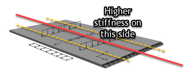
3_yvai6m.jpg
 
Replies continue below

Recommended for you

The stiffer side will draw more of the live load. However, if one side is stiffer, it likely also has different dead load and capacity, so you'll probably have to check the capacity/demand ratio at multiple points.

Rod Smith, P.E., The artist formerly known as HotRod10
 
What if the stiffness is still higher on the right, and the same side sticks out longer than the left? Would it then be conservative to put all the load on the stiff side instead of the less stiff side?
 
It could go either way, I suppose. Generally, moments are higher for longer spans and stiffer sections. Of course stiffer sections are typically also stronger sections, For continuous spans, the negative moments over the interior supports are generally larger.

If the bridge is not symmetrical, there may be several possibilities for the critical sections, including locations where the section changes.

Rod Smith, P.E., The artist formerly known as HotRod10
 
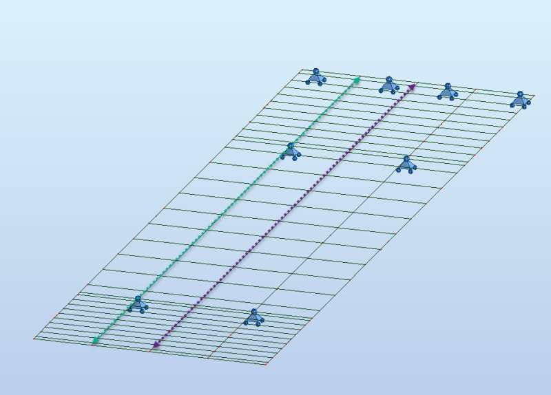
In this case for a beam element model; would it be most conservative to put all the vehicle loads on the purple or green path? I am thinking it must be the purple one as its in the middle and the green one has supports directly underneath its path.

1_egdqdp.jpg
 
If there are just two girders, then the load is the same.
 
So, one end is a cantilever with 2 supports and the other has 4 supports under the end? 2 main girders with transverse stringers? Do you have uplift restraint from the stringers all the way down into the foundation? Looks like you're going to need it.

With that strange configuration, I'm not even going to proffer a guess as to what load positions would produce the controlling capacity/demand ratios or load ratings. You will probably need to move the truck along the bridge in small increments as far out on the cantilever as it can go.

Rod Smith, P.E., The artist formerly known as HotRod10
 
if this is a model ... put the load where it belongs and let the model sort out the stiffness issues.

"Hoffen wir mal, dass alles gut geht !"
General Paulus, Nov 1942, outside Stalingrad after the launch of Operation Uranus.
 
rb1957, it's supposedly a model for a highway bridge; there's numerous possible locations for a truck, and unless it's really small, typically multiple trucks on the superstructure have to be considered.

Rod Smith, P.E., The artist formerly known as HotRod10
 
I get that ... but we seem to be saying do I apply my load over the softer structure or the stiffer one ? If these are two lanes, wouldn't you apply load to both ?

"Hoffen wir mal, dass alles gut geht !"
General Paulus, Nov 1942, outside Stalingrad after the launch of Operation Uranus.
 
I get that ... but we seem to be saying do I apply my load over the softer structure or the stiffer one ? If these are two lanes, wouldn't you apply load to both ?

Yes, but you'd also need to apply the loads separately, since for some points along the members, 1 truck may be more critical than 2, especially after the multiple presence factors are applied. They account for the improbability of 2 very heavy trucks being in the exact worst positions for a particular member at the same time, so there's a 20% increase in the load effect of a single design truck, relative to the effects produced by 2 design trucks.

Rod Smith, P.E., The artist formerly known as HotRod10
 
bojoka4052,
Isn't this just a variation of your previos question where you asked for help to be able to reduce the load combinations for this bridge. You got some questions there that were never answered.

I think that the question you ask can't be answered in general. You need to define what result you want and where in the bridge you want it. I understand that you are looking for a shortcut, but I don't think it exists.

Thomas
 
bojoka4052 said:
In this case for a beam element model; would it be most conservative to put all the vehicle loads on the purple or green path?
I think you are using Autodesk Robot Structural Analysis, correct? If so, you can use Loads> Special loads> Moving loads.
 
get that too. so of the three loadcases (2 trucks, LH truck, RH truck) can you say that RH truck is more critical if it is stiffer (or more flexible ?) and save yourself one load case ? I don't think so, and even if it was, is it really worth the ensuing debate ?

"Hoffen wir mal, dass alles gut geht !"
General Paulus, Nov 1942, outside Stalingrad after the launch of Operation Uranus.
 
I think we're in agreement here, rb1957. I think I misunderstood your statement "put the load where it belongs" to imply that analyzing a single load position was sufficient. By the time I figured out that's not what you were advocating, it had become a debate.

As hoshang suggested, the trucks need to be applied as moving loads, occupying multiple different transverse 'lanes', both individually, and with multiple trucks on the bridge. Combining multiple trucks is no simple task, since each assumed to be a 10' wide loading pattern within a 12' wide lane, assuming that the lanes may be striped anywhere. This is why typical bridge design applies wheel fractions or distribution factors to a girder line analysis. That probably won't work here.

Rod Smith, P.E., The artist formerly known as HotRod10
 
Status
Not open for further replies.

Part and Inventory Search

Sponsor