Eng-Tips is the largest engineering community on the Internet

Intelligent Work Forums for Engineering Professionals

What is the reason the circular holes are equipped with tightening bolts? 5

Status
Not open for further replies.

Znjmech

Mechanical
Dec 19, 2016
94
0
0
IT
Hi All


Usually in some designs that contain a hole on the part, that another shaft is supposed to pass, I see that the hole has a bolt near outside its perimeter that tightens the circle to lower radius. in cases it happens that if the hole part is cicular, it's made from two semi circles and is bolted together. what is the reason for this ?
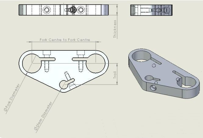
4519814_orig_yoxfkq.jpg
 
Replies continue below

Recommended for you

Thank you guys for the great responses. jgKRI I just could not follow your points on the diaghram. The application is vaster in machine making, I was mostly searching to know more reason apart from fixing in one point using pinch bolts
 
This allegedly is an OEM MV Brutale upper triple clamp.

A few decades back the finest handling, best suspended off road motorcycle did it as shown in the attached image.

The triple clamp gripped the large nut, after the nut was tightened to clamp the TC against the bearing adjusting nut.
For those Timken bearings the adjustment was not a torque, but ~ zero clearance and absolutely minimal increase in rotating torque.
Some bikes had split top nuts, so when pinched by the TC, the split nut likely compressed and the threads gripped the stem.
I'm not real keen on threads ever being in the load path to provide location, so look at the axial clamping as the main preventer of klunks and even micromotions that would fret and wear things out in time.
 
TMoose said:
Are those really caged ball bearings, not taper roller bearings?

Yes, a lot of motorcycle headsets use ball bearings.

TMoose said:
"The inital preload is pretty low- the torque spec for the lower ring nut is 38 ft-lb."
I think 38 ft-lbs is an initial seating torque, to be loosened, then The final, operating torque is back down to 10 ft-lbs according to that diagram. Even zero rpm rolling element bearings don't think much of big preloads .

You're correct that the two torques are initial (to ensure bearings are seated) and then the nut is backed completely loose, and tightened to 10 ft-lb.

The big nut that actually goes into the upper clamp is not shown in that drawing- it is the one I referred to in my earlier post, that a lot of race mechanics torque hand tight + 1 turn. This nut sees very little load in service.

TMoose said:
Is the stem a cylindrical diameter inside the clamp? Does the upper clamp slip off stem at disassembly? I think that the big nut is torqued to reduce/prevent micromotions of the triple clamp on the stem or vice versa. In time using reduced torque may result in fretting and wear of several surfaces there.

In the bikes I have experience with, yes- the steering stem is cylindrical, and the upper clamp does not have a pinch bolt. I would not disagree that preventing fretting between the stem and triple clamp is probably why the big nut is there.

I will say that I've seen chassis that have hundreds/thousands of racing laps on them with the big nut hand tight +1/4 turn, and I've never seen a stem with fretting. The caveat there is that in some ways chassis loading on a race bike is less severe than a bike that does a few thousand miles on public roads.
 
The answer to the question is they are there to clamp. The slots weaken that area somewhat so the material will move enough to allow the bolts to
pinch the holes tighter. I guess that is what you were asking.
 
Guys
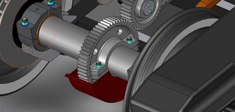
another application I found about this cutting a circular profile in half and re-bolt it is in Train bogie :


boggy_htqdbv.png


The smaller gear behind it is not cut this way though
 
Status
Not open for further replies.
Back
Top