Eng-Tips is the largest engineering community on the Internet

Intelligent Work Forums for Engineering Professionals

What kind of 2 VT Connection is this? 1

Status
Not open for further replies.

thermionic1

Electrical
Nov 30, 2018
311
0
0
US
Once in a while I venture outside the comfort zone of utility work where good quality drawings and relay settings are a given. My latest adventure takes me to a water treatment facility that was built over 50 years ago, expanded multiple times and has very poor documentation. I was there to install some SEL relays, a GPS system and RTAC, so they can get a better handle on the numerous mis-operations that plague the plant in blackouts several times a year. My adventures so far have found a high impedance bus differential secondary circuit that had B&C phases rolled (and the PVD relay settings jacked up on those phases), multiple DC systems mixed together, the list goes one. Our outages per feeder were time restricted meaning get the old electro-mechanical relays out and the new SEL relay installed in less than 5 hours which is a challenge with the very poor documentation available.

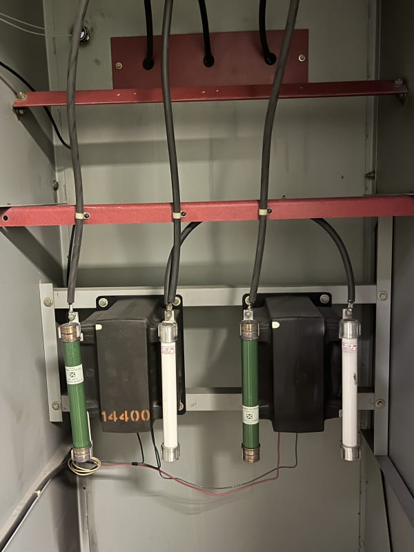
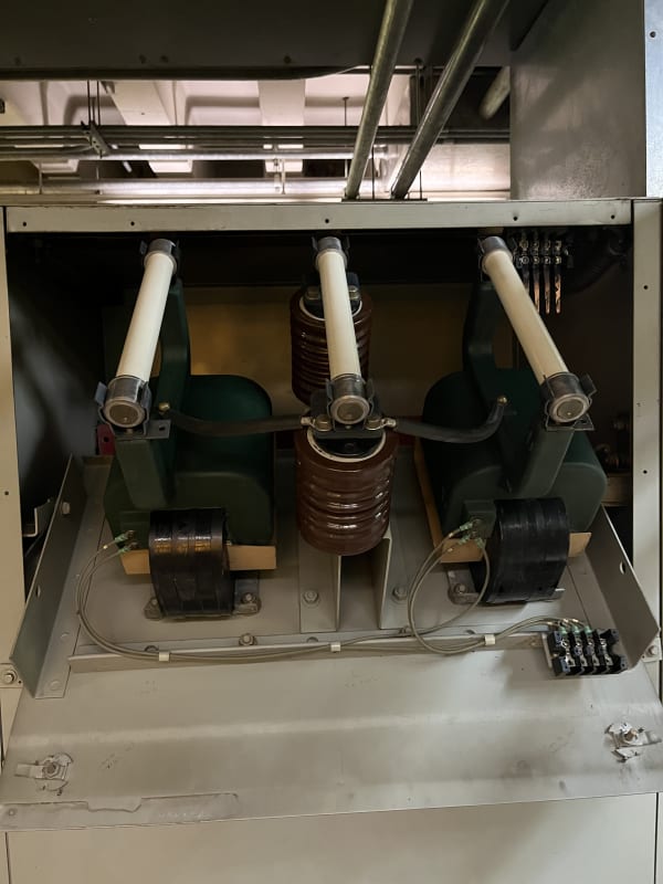
After installing the new relays and checking in service values, I could not get the relay happy with the Current to voltage phase angles. My PAM batteries took a crap, so I was relying on the metering values from the SEL-751. Additional investigation after shutting down a feeder revealed what is shown in the photographs. This switchgear is Main Tie Main and each bus has a 20MW generator connected. My eyeballs are telling me this is not an open delta connection, as shown on the prints. Trouble is, there are multiple sets of VT's that follow this unusual connection. For reference, the black VT's are showing H1 as the polarity marker. While difficult to t see, the LV connections have the X1 polarity marker on the left side terminal. The green VT's show the same connection, with the fuse indicating H1 and the top LV connection being X1. The black VT's are formerly the utility metering devices, while the green VT's are for the bus. The green VT's feed a variety of analog Watt, Whr, Var meters & transducers that are read from the control center for the plant (they have about 50MW in various generation sources). I'm keenly aware that changing one thing to make it correct will have a definite trail of other things being changed, including the daily readings made by maintenance personnel on their clipboard readings for various electrical quantities. I've also found a unique quirk in the culture at this facility in which if you are in the same general vicinity as a device and else in that area has a problem, it's on you to prove your own innocence.

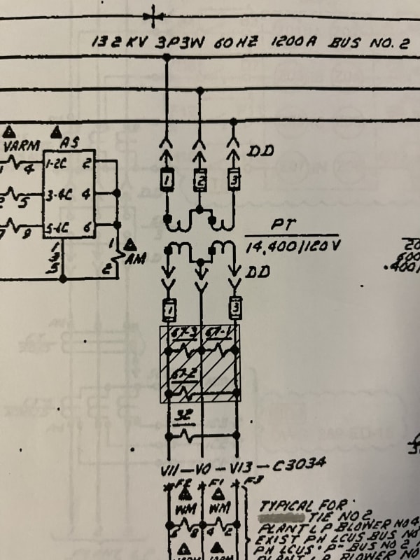
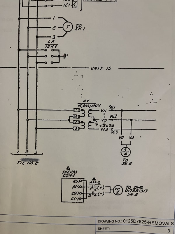
My question is, are the VT's shown in the picture following any logical type of connection? The black are Left to Right ABC (mounted in front), while the green VT's are located in the back, so Right to Left is ABC. The AC schematics shown are for this installation and clearly show an open delta connection.


IMG_0946_-_Copy_nex1wy.jpg
IMG_0954_-_Copy_fojlgz.jpg
IMG_0955_-_Copy_klten8.jpg
IMG_0950_-_Copy_po0tyv.jpg
 
Replies continue below

Recommended for you

A typical open delta will be A-B and B-C,
That connection is A-B and C-B.
A conventional connection on 120 Volt secondaries will give 120 Volts, 120 Volts opposite polarity and 208 Volts across the open side.
If the secondary connections are reversed on one PT, you will get usable voltages and phase angles.

There is a remotely similar and very rare distribution connection called an open wye or Winnipeg connection.
The Winnipeg connection will produce three phase wye with a neutral from two phases and a neutral.

--------------------
Ohm's law
Not just a good idea;
It's the LAW!
 
The culture of "if you are the last one to touch it, it is your fault" is actually common. Namely if no one bothers to update the prints.
It sort of looks like they never got the as built prints. This is common when the contractor is about to go into the red on the project. The common thing to cut at the last minute is finishing the as built prints.
Normally this is toped off by maintenance people who also don't understand the value of good drawings, or management that does not give the time of resources to correct the drawings. Also quite common.

But it does look like the connections have B and C phases reversed from the drawings. But this can be corrected by reversing the secondary side.
 
In the first picture, the VTs are connected in an open-delta...just in a non-conventional manner.

If you look at the secondary connections on the right VT, they are reversed to mimic the primary connection.

I have not idea why the didn't connect H2 of the left VT to H1 of the right VT to B phase, as is normally done. But they either followed the same principle on the secondary wiring or changed it after the fact to compensate for the weird primary connection.

Aside from being non-conventional, I would have a concern about B-phase connection passing behind the C-phase connection behind the glasstic strip. I can't really get a depth perspective from the photo, but it doesn't look like a good practice to me.

I have no idea what's going on in the 2nd set-up. Those look like single-bushing VTs to me, unless the H2 terminal comes up from under the fuse holder too, but I've never seen anything like that and I can't imagine how one would design something like that to pass impulse, and PFWV between the primary terminals.

 
I would agree with scottf, the first picture matches both schematics electrically, assuming that X1 terminal is the left screw. It doesn't match the first schematic electrically, but does match the second schematic. On the first schematic, the right PT should has the H1 and X1 dots on the right side.

The second schematic and second picture seem to match assuming the X1 terminal is the top screw.
 
LionelHutz....the problem in the 2nd picture is that the VT appears to be a single-bushing VT...since there is only one fuse and the connection that can be seen from the B phase to both VTs is at the base of the fuse holder, be connected to the same terminal on both VTs, and both VTs seem to be oriented in the same direction.
 
I just realized the 2nd drawing doesn't match any physical connection either. The dots on the drawings should be on A and C to match these connections.

The 2nd picture VT type is odd to not seem to be 2 bushings, but it must be OK. The connection just has H2 going to B phase on both VTs so wire the secondary to match - A output to X1, B output to X2-X2 and C output to X1. Same as the first picture. The secondary appears to be correctly wired.
 
I'm headed back to the site tomorrow. In the mean time, just for everyone's entertainment, I got a call today from the plant...blaming me for not being able to sync one of their turbines. I politely explained I hadn't touched anything and the VT's I was investigating were on bus 2 and the turbine that wouldn't sync is on bus 1.

I forgot to mention that when I was measuring voltage on the bus 2 VT's, I had ~115V A-Gnd, ~115V C-Gnd and ~230V A to C. I thought that may have been a secondary polarity issue, but I checked the primary and secondary polarity markers as well as the GE JVM-5 data sheet for the black VT's and the polarity dot on the secondary is on the same side as the primary polarity marker.

The SEL-751 relays we're installing have comprehensive metering as well as a setting for Wye or Delta PT's and phase rotation. I could not get the currents and voltages to be happy, meaning negative sequence voltage and current readings on each relay to measure roughly zero with swapping the VT signals or changing the phase rotation settings. We just finished upgrading the substation that feeds this switchgear, which also has open delta VT's and I was able to make everything match up phase angle wise, as well as the sequence components. The one possibility I haven't checked is that the CT's, although labeled C1,C2&C3 at the shorting terminal blocks may not be correct

One other set of VT's caught my attention. There was a generator on bus 2 and it has 3 VT's in the switchgear, located on the generator side of the breaker. These VT's are connected Delta-Wye. I haven't been able to find detailed drawings for the generator, but I would assume the unit would use these for syncing against the green VT's which are shown as open delta. All the larger generators I've been around had open delta VT's exclusively and certainly the ones involved in synchronizing.

Already pack in the truck is my phase angle and rotation meter, with new batteries which I hope will aid in troubleshooting. I may even go across the street to the utility sub that feeds the plant and make a few measurements on the bus VT's that feeds them.

Scottf was correct about the green VT's. H2 is indicated on the connection to the black jumper.

Thanks for the tips.
 
Be wary of wye and delta PTs when synchronizing.
I found a small diesel generating plant (5 sets, total installed capacity 2.2 MW) where a main generator breaker would often trip when synchronizing.
After synchronizing, the synchro-scope would jump to 2 o-clock.
The bus bar reference voltage was taken from a wye connected PT.
The generator reference voltage was taken from a delta connected PT.
You have probably seen crews with one or more persons who are smart and confident, and other slower persons who aren't as smart and are somewhat hesitant.
The confidant operators had a lot of trips before they could get a set online.
The slower hesitant guy almost always got online at the first try.
The smart operators threw the breaker when the 'scope hit 12 o-clock exactly.
The hesitant guy was slower to close the breaker and by the time he closed, the set had drifted closer to synchronization.
They had been operating like that for several years since the plant was installed.

--------------------
Ohm's law
Not just a good idea;
It's the LAW!
 
Follow up:

The black VT's (incoming line) were rewired on the primary and secondary sides and connected to a single relay. I had my phase angle meter (and battery), and it was then determined that Va and Ic, Vb & Ib and Vc and Ia seem to match. The currents were wired from a terminal block that had existing C1,C2,C3 &C0 connections to respective Ia,Ib,Ic & In connections on the relay. We had tentative plans to open the breaker, swap the currents and so on.

A colleague reminded me that we have a device called a phase tracker (Phase Tracker and we have access and permission from the distribution company to check at the transformer that is 1/2 lines that feed the plant.

Additionally, we have SEL RTAC's set up in 3 different stations, all connected to the same plant LAN. I'm also planning of using the RTAC to tunnel through to remote relays and the synchrophasors features of the relay with a delayed trigger time to check various source and load breakers. Once we have the proper phases identified I can easily check remote stations for plausibility.

Waross - I saw those 3 phase VT's in a Delta Wye configuration and wondered the same. I don't ever recall seeing anything other than open delta VT's on larger machines. Our smart operators here blamed me for messing with their HMI indications. When I dug into it, someone in the past had cobbled on ice cube relay onto their red light. Ice cube was to feed PLC and indicate open/closed/tripped. Despite me telling them that I grabbed a spare 52a for my relay, they insisted it was me. Their faces, when I found the ice cube, disconnected since who knows how long. So they were hard at work monitoring their statues for years and only after a new relay was installed did they notice their micky mouse set up in their control panel was not wired. Oye vey!

While I was there last week, configuring the RTAC, I heard a breaker trip. A walk down the isle indicated that the Gen #1 breaker (which was running at the time) tripped. A few minutes later, it closed. The generators have 50+ year old EM relays that are located in the control room (upstairs), behind the mimic and metering board. Two weeks previous I got a call (politely blaming me) for the inability to sync Gen #1 (on bus 1), because they heard I had rewired VT's (incoming line on bus 2). A few questions to some folks at the plant revealed that there is no auto sync, just manual, which I hope is supervised by a sync check. They were eventually able to sync. BTW, Gen #2 on Bus #2 is permanently OOS. "It blew up" I'm told.

So I start asking more questions. Do they log the trip times? Do they record relay targets (flags), do they reset targets? The word I got today was that the trip last week was due to loss of excitation relay. They also insisted they they weren't running (so what was that open breaker I saw after hearing the trip?) Luckily, I had texted the project manager (have times) and they closed back in 7 minutes later. No investigation, just slam it back in. It's just a big cluster here. The turbine that tripped was serviced (removed from site) a few years ago. The excitation was upgraded to a Basler unit in 1995 and does not sound like a DECS or similar with advanced metering and monitoring capabilities. I plant on check on these things later in the week.

This is quite an unusual set up. The turbines and all the relays are GE, circa 1970. The actual switchgear is Allis Chalmers. There are 15 cubicles with 13 breakers. The drawings, which I was able to find after installing 7 relays without any drawings, are contained in 3 'typical' packages which are the DC and wiring combined in a single drawing. No cubicle to cubicle drawings, CT's obviously changed (drawing shows dual ratio and terminal block has 5 wires per CT). Just a mess. The original design had the trips in series with a truck operated contact (who does that and why?).

When I was just starting out, I was fortunate to have a coworker/mentor that came out of college in 1974 and went right into the GE field engineering program. He knew everything about everything and explained to me that his first several years at GE were spent working in various GE factories learning everything from the ground up. Once he mastered motors, it was transformers, switchgear, protection and so on. I would have assumed that when GE built the turbines, they had someone similar doing check out. I'm seriously beginning to doubt this happened. I'm starting to think that whomever did the checkout buzzed through the instrument transformer circuits with an ohmmeter and because it beeped from point a to point b on the secondary wiring, that meant it was good.

Maybe Gen #2 was taken out by too many bad syncs? Maybe the operators that manually sync are seeing Open Delta bus VT's vs. Delta Wye as you have seen? I have the project engineer searching for microfilmed drawings and hopefully the GE manuals that have the original relays settings for the generators. I'm going to try to verify bus and gen VT's as well.


Status
Not open for further replies.
Back
Top