Continue to Site

Eng-Tips is the largest engineering community on the Internet

Intelligent Work Forums for Engineering Professionals

  • Congratulations pierreick on being selected by the Eng-Tips community for having the most helpful posts in the forums last week. Way to Go!

What might happened if f's is negative 9

Status
Not open for further replies.

XinLok

Civil/Environmental
Oct 22, 2019
77
If we take a concrete beam with the following dimensions:
Mu = 136.77 k-ft
b = 12 in
d = 8.43 in
d' = 3.56 in
f'c = 4000 psi, fy = 60,000 psi

According to ACI code, I have to deal with a Double reinforced concrete cause M max = 58.27 k-ft < 136.77
Screen_Shot_2020-09-19_at_5.16.02_PM_gywjpp.png


If I continue by using excel to avoid writing everything here, I will get f's < 0 cause c - d' < 0

Screen_Shot_2020-09-19_at_5.18.18_PM_gfhq6q.png


If I stick with the dimension above, what will happen and what does mean f's negative?
 
Replies continue below

Recommended for you


Look to your c and d' values..the neutral axis seems above the compression steel ..


I was planning to upload the following picture but again pressed to submit ..The picture clearly shows the doubly reinforced rectangular sections.


double_reinf_beam_lc70pz.png
 
F's can be negative it just means the the strain compatibility worked out such that you have a small compression block so the upper layer of steel is in tension. This can happen if your section is larger than you really need or under-reinforced. Compression steel is a way to get back to a tension controlled section when you end up with too much tension steel and don't have the option to make the cross section larger.

My Personal Open Source Structural Applications:

Open Source Structural GitHub Group:
 
XinLok said:
If I stick with the dimension above, what will happen and what does mean f's negative?

It means your analysis is invalid. You can't stick with the dimensions above; you will need to select more realistic dimensions. Try increasing d and decreasing d'.

BA
 
Looking at your calc closer it looks like your section when singly reinforced was well under capacity and you may have mistakenly followed the procedure for a doubly-reinforced section with compression steel as you added your second layer up near the top of the section instead of down near the bottom. F's is negative in your calculation because the formula you used assumes that the steel will be in compression but your cross section needed it to be tension steel for strain compatibility which is why it is negative in your calculation.

I would disagree with BAretired that your analysis in invalid, in fact your analysis is valid and has shown you that your section is under reinforced and needs more tension steel towards the bottom of the section not the top.

Try increasing d' to be 7.43 or whatever distance satisfies the minimum clear spacing between bar layers.

My Personal Open Source Structural Applications:

Open Source Structural GitHub Group:
 
Celt83 black, BA red:

Looking at your calc closer it looks like your section when singly reinforced was well under capacity (you can say that again) and you may have mistakenly followed the procedure for a doubly-reinforced section with compression steel as you added your second layer up near the top of the section instead of down near the bottom. (Not true. He assumed d' of 3.56" which puts the compression steel near the middle of the section) F's is negative in your calculation because the formula you used assumes that the steel will be in compression (that is true) but your cross section needed it to be tension steel for strain compatibility which is why it is negative in your calculation. (but you put your compression steel below the neutral axis of the section, so the formula was invalid.)

I would disagree with BAretired that your analysis in invalid, in fact your analysis is valid and has shown you that your section is under reinforced and needs more tension steel towards the bottom of the section not the top. It's not under reinforced. As1 + As2 = 5.409in2. It is over reinforced. The concrete section needs to be substantially larger to resist this moment.

Try increasing d' to be 7.43 or whatever distance satisfies the minimum clear spacing between bar layers. That would make things even worse as the compression steel would be at the bottom of the section.

BA
 
BAretired said:
(Not true. He assumed d' of 3.56" which puts the compression steel near the middle of the section)
maybe but don't know for sure as op never mentions the overall section height, it's close if you assume d+1.5" = H.

BAretired said:
(but you put your compression steel below the neutral axis of the section, so the formula was invalid.)
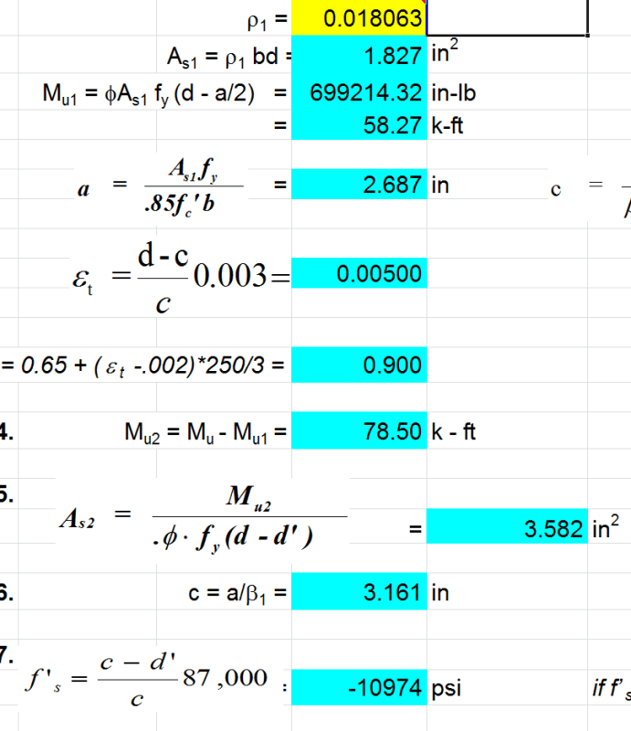
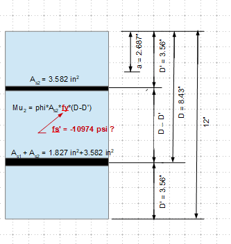
It's not compression steel, as confirmed by the calculation the steel is in tension and it should be because the section is both too small and substantially under reinforced.

BAretired said:
It's not under reinforced. As1 + As2 = 5.409in2. It is over reinforced. The concrete section needs to be substantially larger to resist this moment.
If the extreme steel strain is > than 0.004 then the section is still tension controlled and not over reinforced, there is such a large amount of steel because again the section was under reinforced, and the d' puts the next layer of tension steel at such an inefficient location that it takes a good amount more As to produce the required moment.

BAretired said:
That would make things even worse as the compression steel would be at the bottom of the section.
It's not compression steel, the cross section is screaming that it needs to be bigger or in the absence of increasing in size have more reinforcement at as low an elevation as possible.

Edit:
We agree that the section is too small. If you assume that the overall cross section height is 12" then yes to get near that Mu you will need compression reinforcement while at the same time nearly tripling the tension steel area.

OP, your analysis is invalid because it appears you didn't re-calculate the neutral axis depth after considering the second layer of steel you are trying to add, doing this you'll find that the steel is in tension and phiMn is still substantially less than your Mu.

My Personal Open Source Structural Applications:

Open Source Structural GitHub Group:
 
A concrete beam with b of 12", d of 8.43" and tension steel of 5.4in2 is over reinforced by definition. A beam is over reinforced when the area of tension steel exceeds balanced reinforcement, which this one clearly is.

Dimension d' is the distance from the compression face to the c.g. of compression steel by definition. In this case, d' = 3.56", nearly half of the effective depth, d.

The above are not opinions; they are facts.


BA
 
What is the limit on neutral axis depth in ACI-318? In the 2019 version, it looks to me like c/d<0.38 approx, based on table 21.2.2 & clause 9.3.3.1, which sounds about right.

Given that limit, the depth of the section, and the required location of the compression-side reinforcement (cover plus stirrups), it seems that you can't actually get the 'compression' reinforcement into the compression zone. Double-reinforced design just isn't an option without increasing the depth or reducing cover (as per BAretired).

I'd also check deflection carefully.

 
I think as well to add to what others have said. Sometimes you're better to solve these things frm first principles, rather than reliance on an equation that with certain configurations becomes invalid.

i.e. create a spreadsheet that recognises the bar strains and hence whether it's in compression or tension irrespective of where bars are located in the cross section.
 
BA respectfully I disagree with your statements in the context of ops post.

BARetired said:
A concrete beam with b of 12", d of 8.43" and tension steel of 5.4in2 is over reinforced by definition. A beam is over reinforced when the area of tension steel exceeds balanced reinforcement, which this one clearly is.
An over-reinforced section is that in which the extreme tension steel strain remains below the yield point while the ultimate concrete strain is reached. OP's outer most tension layer reaches a strain of 0.005 > 0.002 yield strain as such the section is not over-reinforced. I agree that they have too much steel in the section and will require too much steel to achieve the note design strength but as it stands by definition the section is not over-reinforced.

BARetired said:
Dimension d' is the distance from the compression face to the c.g. of compression steel by definition. In this case, d' = 3.56", nearly half of the effective depth, d.
I concede that every text book and guide including the one OP followed will denote d' as the distance from the extreme compression fiber to the compression steel but in the context of OP's calculation d' is at 3.56" while the Neutral Axis lies at 3.161" as such by definition the steel is on the tension side of the strain curve and is tension steel regardless of the initial intent.

My Personal Open Source Structural Applications:

Open Source Structural GitHub Group:
 
Celt83,

Celt83 said:
An over-reinforced section is that in which the extreme tension steel strain remains below the yield point while the ultimate concrete strain is reached.

With all due respect Celt83, I think you have just defined an under reinforced section. Balanced reinforcement occurs when maximum concrete strain occurs simultaneously with yield in the tension steel. Over reinforcement occurs when maximum concrete strain occurs first.

Whitney established empirically that the ultimate strength of a balanced rectangular beam is, closely enough:
Mu = 0.333f'c.bd2

So Mu(balanced) = 4*12*8.43^2/3 = 1137"k or 94.75'k
In the present case, Mu required = 136.77'k (44% in excess of balanced design)

Balanced reinforcement is not a goal to strive for because sudden, explosive failure is extremely dangerous; a beam should provide a little warning which it will do if the beam is under reinforced and failure occurs as a result of steel strain.

Celt83 said:
I concede that every text book and guide including the one OP followed will denote d' as the distance from the extreme compression fiber to the compression steel but in the context of OP's calculation d' is at 3.56" while the Neutral Axis lies at 3.161" as such by definition the steel is on the tension side of the strain curve and is tension steel regardless of the initial intent.

Please note that d' = 3.56" was not calculated; it was selected by the OP for reasons unknown.

BA
 
Regarding over/under reinforced, BA, you just said the same thing as Celt in a different way.


----
just call me Lo.
 
This calculation seems contained many mistakes. You should list all equations used in the calculation to avoid misunderstanding. The sketch below is based on the data provided, and with my guesses.

image_rc6ofo.png
 
Lomarandil said:
Regarding over/under reinforced, BA, you just said the same thing as Celt in a different way.

Not quite. By my definition, the beam is over reinforced. By Celt's definition, it is under reinforced.

BA
 
Trying to understand the source of the disagreement and think that maybe not everyone is aware that the reinforcement at depth d is (A_s1 *plus A_s2*), and then there is a further A_s2 at depth d'. With (A_s1 plus A_s2) at depth d, it is over-reinforced, even with A_s2 at d' because d' is too close to the neutral axis.

Doing it the way suggested by Agent666, you find that the d' reinforcement is actually in compression but not at yield as assumed when determining the quantity at d'. The neutral axis is at about 5.3" depth.
 
Exactly. If using an assumption (like whatever equation was used) means you have to test that assumption once you've established the force/strain distribution.

Often for example if doing it by hand you might assume compression reinforcement has yielded as an initial assumption, then once you've worked through the strain distribution you check if your strain is over the yield strain. If not go back to iterating stress/strain to achieve force and moment equilibrium for your configuration.
 
Suggest to recalculate the compression block depth "a", taking into account of the added As2. The result might indicate the top steel is in compression, and the fs' obtained previously is correct. Also need to check permissible reinforcing ratio (ρMAX).
 
Steve:
Thanks for that I was focused on just the info op was presenting not actually running thru the calc myself and missed that they didn't do the step of adding the steel areas, which drives the neutral axis down and results in an over-reinforced section.

BA:
Lo is correct you said the same thing I did. If ec=0.003 and es=0.002 balanced, if ec=0.003 and es>0.002 under-reinforced, if ec=0.003 and es<0.002 over reinforced and has potential for sudden brittle failure.


My Personal Open Source Structural Applications:

Open Source Structural GitHub Group:
 
Status
Not open for further replies.

Part and Inventory Search

Sponsor