I am determined to find out the stress level at front frame of motorcycle in worst case scenario. I have prepare two model. One is MBD FLEX body model and another is FEA 1_D element model.
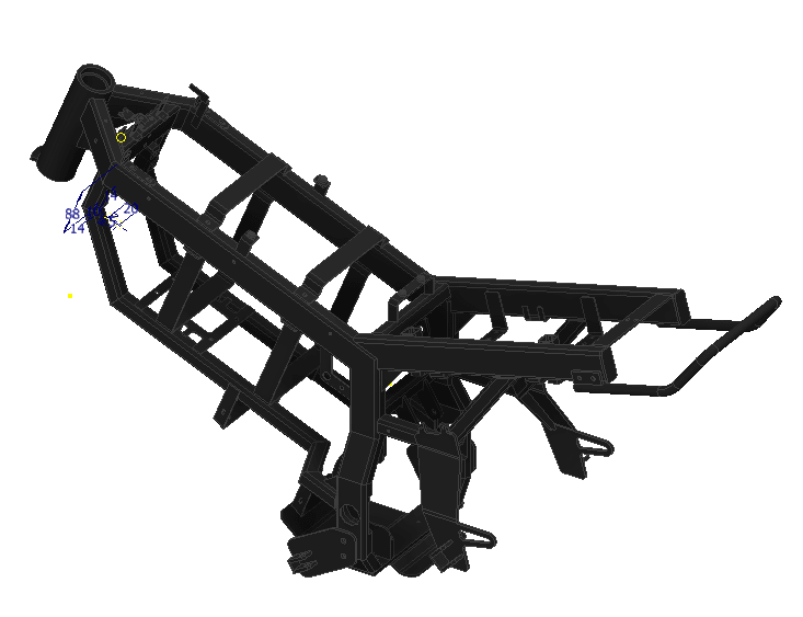
Geometry of Front Frame of motorcycle

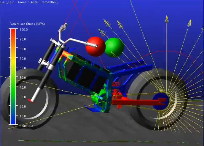
MBD FLEX Model

MBD FLEX MODEL gif
[URL unfurl="true"]https://res.cloudinary.com/engineering-com/video/upload/v1649136545/tips/mbd_gif_i640vs.mp4[/url]
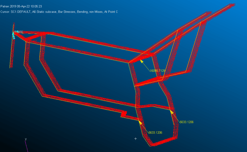
FEA MODEL

From Flex MBD model, I came to know that maximum von misses stress are in the front frame's neck area. I have checked hot spot stress value. It is around 534 Mpa at neck area. I cannot trust this stress level blindly. So I decided to make FEA model using line element( I think line element is the best for this kind of geometry).But the problem is How do I apply constraints and loads in my model?. I have applied constraints in the head tube and loads in the suspension mount and swing-arm pivot points. I don't have much confidence in applying such B.C. What would be the accurate boundary condition in my case? Should I include inertial relief method for this ?
Geometry of Front Frame of motorcycle

MBD FLEX Model

MBD FLEX MODEL gif
[URL unfurl="true"]https://res.cloudinary.com/engineering-com/video/upload/v1649136545/tips/mbd_gif_i640vs.mp4[/url]
FEA MODEL

From Flex MBD model, I came to know that maximum von misses stress are in the front frame's neck area. I have checked hot spot stress value. It is around 534 Mpa at neck area. I cannot trust this stress level blindly. So I decided to make FEA model using line element( I think line element is the best for this kind of geometry).But the problem is How do I apply constraints and loads in my model?. I have applied constraints in the head tube and loads in the suspension mount and swing-arm pivot points. I don't have much confidence in applying such B.C. What would be the accurate boundary condition in my case? Should I include inertial relief method for this ?

![[smile] [smile] [smile]](/data/assets/smilies/smile.gif) .
.