Eng-Tips is the largest engineering community on the Internet

Intelligent Work Forums for Engineering Professionals

What would be the total KWH poeer of my ammonia compressors?

Status
Not open for further replies.

Zainu

Agricultural
Jan 15, 2023
8
0
0
BH
Our IBT (like chilled water tank) has capacity of 1 lakh liters of water, the forward chilled water flow rate is 73000ltrs/ hr, the forward and return temperatures of chilled water are 2dc and 20dc, the load time can be considered as 24 hrs and all compressors are ammonia operated having superheated ammonia temperature of 80dc. The condensors are forced draft type and condensed ammonia temperature is 25dc. Then what would be the total KWH of my compressors?
Should we consider the capacity of water cooled condensors while calculating the power rate required for the above?
 
Replies continue below

Recommended for you

OP claims it's not thread507-501506

OP, you should show some sort of drawing. Your narrative description is confusing, at best. I have to assume lakh refers to 100,000, for example. You say "compressors are ammonia operated" and then "condensed ammonia temperature is 25dc" which seems contradictory. Ignoring that, your water flow's change in temperature would give you the change in energy.

TTFN (ta ta for now)
I can do absolutely anything. I'm an expert! faq731-376 forum1529 Entire Forum list
 
Draw a diagram of your cycle/process, draw a box around it, and perform an energy balance for all the mass/energy flows entering and leaving the box.
 
59187F95-2D44-4917-8EAA-52E3242832D9_rhvlvk.jpg
 
Tell us what type of compressor : 2stage reciprocating I suspect.
Why are you turning to E-tips for this info? There are folks who can help with this laborious calc but we normally only provide tips. Show us your solution workup. Or have you lost hope getting a solution ?
 
[URL unfurl="true"]https://res.cloudinary.com/engineering-com/image/upload/v1674104756/tips/Untitled-1_idthfb.pdf[/url]

Honestly, I'm first time time doing the calculation in a field, after my technical graduation in dairy technology. Currently I'm representing Quality Assurance Laboratory of a food manufacturing company. I'm doing the calculation because of the management request to find the solution why we can't get the proper temperature even in the winter?. Then I tried to sort out many data which is currently available and trying. The attached diagram is the actual flow diagram of our ammonia refrigeration system and I'm doing the back calculations by using the chilled water (IBT) IN and OUT temperatures.
I'think you understood my difficulties as I'm not representing an engineering position in the company instead of representing QC LAB.
So, when you ask more details and technical terms regarding the system, I may have to go deeply to find.
Hope you professional people can help me, that's why still I'm here.
The simplified diagram is one which I posted earlier.
If you people can share any article/online reading etc. regarding this type of solution, please share. I love to read and study more.
I look forward for your kind responses..
 
Zainu,

Sorry for my indiscression :) You have started with a rather big elephant :)

As i read your diagram you not only supply the chilled water with NH3 from these compressors - but also a lot of other systems. So you couldnt calculate your compressor power just from the tanks.

So, unless your NH3 pressure is much lower than intended then i think that the problem must be on the heat transfer side in the tanks - not the avaiable compressor power. My guess is that you simply dont get enough NH3 through the cooling coils in the tank (i.e. the coils are too small).

Unfortunately eng-tips is not a free consultancy service. We cant do a complete review of you system for you just point you in a possible direction (speaking for my self i guess).

--- Best regards, Morten Andersen
 
Hi,
Why don't you talk to your manager and ask him to assign this work to your process engineer/manager?
It's a big task. Sorry if you find my answer rude, not my intention.
You will need to get a Mollier diagram for NH3 and/or fluid properties data (thermophysical data) for thermal balance, a link is attached.
Good luck.
Pierre
 
Nice schematic, but doesn't tell you much or where you can measure flow, temperature or pressure.

You appear to have 2 x 110kW, 1 x 90 and 2 x 55kW compressors in the main cooling cycle. Just measure power consumption from the running compressors will tell you what energy you're consuming.

There are many reasons why the plant is not performing and trouble shooting is sometimes not easy as you don't have all the data.

First thing to do is understand what SHOULD be happening by looking at the technical design from the vendor and trying to see which parts are not operating as they should or if the water flow is higher than it was designed for.

So first find all the technical data you can about the design and operation of the system as supplied by the vendor or designer of the package. then work away from there.

Remember - More details = better answers
Also: If you get a response it's polite to respond to it.
 
At my plant we have 3 NH3 heat pumps. But they are simple compared to your system. IMO if your cold section (the ice making)is not affected then it must be the cooling coils for the IBT that are insufficient. This can e.g. be due to design error in original design, that you may have increased water flow beyond capacity or due to fouling on the outside.

--- Best regards, Morten Andersen
 
@Zainu

It's great that you are willing to take on this challenge, dig deeply and are trying to learn.

Having said that, this is a really complex system of refrigeration equipment. If you look at MortenA's history here on Eng-Tips you will see that he knows a lot about refrigeration. If he says it's complex then it's really complex.

For something like this I'd expect the facility to have a full-time operating engineer to look after the care and feeding of this equipment. At the very least have an on-call maintenance and service contract with a local firm to take care of it. Is that not true in your case?

Does the 2022 date on the system diagram indicate the date this system was build and put into operation?

Did the system ever work as intended?

For something this complex there should have been contract requirements for commissioning. The contractor that built this should have been obligated to demonstrate that the equipment works the way it was intended. Did that happen?

There should be a commissioning report that lists how everything was adjusted after commissioning.

There should be a file cabinet full of technical information about all of the equipment.

Even with all of this information available, I'd expect it to take a lot of time for an experienced refrigeration engineer to figure out and correct the cause of your problem. This simply seems far too challenging for a relatively young and inexperienced non-engineer to figure out, even with the help of "the internet". There is nothing negative about your desire or ability in that statement. Given time and training and experience you could very well become the experienced expert needed, but that is not likely to happen in the time that management wants.
 
Presume the problem is with not getting the exit chilled water down to 1-2degC ?

Looking at your schematic, it seems the problem may be in IBT 1A/1B (as @MortenA has indicated). Getting water down this close to freeze point is not possible unless you have very high heat transfer coeff and no dead ends on the water side. These are plain coils immersed in water which is agitated but external htc may not be high enough to prevent icing on the water side. Hence the ice acts as a large resistance to heat transfer to the cold subzero ammonia evaporating on the tube side, which is floating on the HP stage NH3 compressors.

Can think of 2 possible solutions:
A)Use a pumped scheme for chilling at IBT 1A/1B with a welded plate HX in order to get high heat transfer with no dead ends. Where water is taken from a warmer part of this tank and returned to a cooler side of the tank. Recirculation rate to be kept constant with dedicated recirc. pump to maintain high heat transfer coeff on the water side. Remove the current chilling coils in this tank.

B)Replace the entire chilled water circuit with a propylene glycol water mix which has a lower freeze point. For example, for a 30% wt prop glycol water mix, freeze point is -14degC, while that for 20% solution, it is -8degC. Possible disadvantage of this scheme is the lower heat transfer characteristics of prop glycol/water mix, which will mean higher circulation rates, and more heat transfer area to compensate.

I would tend to go for solution A due to the thermal duty risks throughout the entire plant associated with solution B. With this solution, also see if you can raise the temp of evaporating NH3 by introducing a backpressure control valve on the discharge of the NH3 accumulators on this IBT 1A/B - this would enable less risk of water ice on the chilled water side of the plate HX. Ask the plate HX designer to give you a worst case estimate for the surface/film temp at the cold end of this HX, and if necessary, maybe change out to a 10-15% wt prop glycol - water mix to give you a little more room if you must have chilled water at 2degC. Running the plate HX in co current mode rather than the conventional full countercurrent mode will also help to prevent icing on the chilled water side.
 
By comparing the value for ((cp.mu)^0.14).(k^0.86) for water and 20% wt PPG/water at a mean 13degC, I see there is only a 5% reduction in heat transfer "effectiveness", so it should be possible to use 20% wt PPG/water instead of plain water. Which would you much more room to allow an operable design for the new plate HX.
 
George makes an excellent point.

Maybe try setting the temp control to 4 or 5 C and see what happens.

You might get better overall cooling.

But you need to able to measure flow to figure out what is happening.

Remember - More details = better answers
Also: If you get a response it's polite to respond to it.
 
Very sorry for my late response.
I'm very thankful to you all for your kind responses and suggestions.
Here i would like to say something more,
1. Why the management given this task to me, even though I'm QA person instead of from engineering side ?: The actual situations you can't believe here,but simply and honestly the reason is nobody here having the capacity to do the calculations/scientific base root cause investigation. But, i accepted this task since I love to learn more and more in any part of engineering and has some skills to survive. So let's leave the management side and go to the solution.

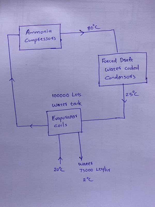
2. The management question was, why we are not getting the required temperature (<7dc) even in the winter, also even though there was good temperature in IBT (around 1dc): (First of all, this was not a sudden problem,having years ago. Just leave the reasons). Then I tried to find out our refrigeration capacity by using the available data. I know the point, 1.2 hrs. of time is required to reach the IBT temperature (1 dc) when we start cooling (with all compressors) of newly filled water of 30dc (using borewell water after R.O treatment). By using this, i tried to find out the capacity in winter. Then I tried the actual heat removed by using the chilled water IN & OUT temperatures and so and so (report attached).

3. Why I asked here about my power of my ammonia system ?: Because, I want to know, how can we calculate with basic equations. To get some threads to do some workouts myself.

4. Why I submitted the report without getting proper answers from the experts like you distinguished peoples?: Like I said in the first point, management don't know the difficulties behind it as a QA person instead of an engineer and management was very hurry (honestly I'm first time approaching to a practical situation regarding this refrigeration in my life). The management won't ready to pay big amounts.

5. What's next?: Now i submitted the report and management will be satisfied since there is nobody to object even my report (because I'm not a engineer to do so.)
But, after accepting this challenge, I'm very interested to study more and approach the issue some more deeply. I'll try whatever possible to do.

So here I'm attaching a relevant portion of my report about this problem before you all. I'm happy to here from you all to learn more. I know there are many mistakes but I was hurry to finish the task, so didn't thought more. But you can teach me about my mistakes.
and still I'm confusing the role of condenser in calculating the power of ammonia refrigeration system. Love to here from you.

Thank you all.

 
 https://files.engineering.com/getfile.aspx?folder=d5615c9d-4e35-4469-952f-754caebab2ae&file=Cooling_System.pdf
For finding out the cooling capacity of your refrigeration system.

Youd probably start with finding out what cooling capacity the compressors are able to give at your systems running conditions (low stage suction and discharge pressure, High stage suction and discharge pressure, type of refrigerant: Ammonia). Youd need to find the technical information on each of the compressors, or try and ask the manufacturer for it.
Something like: [URL unfurl="true"]https://www.sabroe.com/fileadmin/user_upload/Marketing/Brochures/Compressors/SMC_PUBL-5612_2022_EN.pdf[/url]

When you know the capacity of the low stage compressors. You can then see if your high stage compressors are able deal with the load from the low stage.

When you know the capacity of the high stage compressors. You can then look into whether the condensers have enough heat rejection capacity to deal with the the load from the high stage compressors. Youd need to look for the technical information for the condensers, and use your system running parameters (ambient temperature, humidity).

That should give you a rough idea of what cooling capacity your system is potentially able to give for the low stage and the high stage.

But there are other things to take into consideration, like are the compressors and condensers in good operating condition, have they been set up correctly, is the pipework layout suitable ect...
The manufacturers technical info is normally quite good for learning stuff from and finding out how to carry out some checks.
 
What happened to the manufacturer specification sheets that would have been issued during the installation of the refrigeration equipment. All that details that you are inquiring about would have been provided by the manufacturer. Secondly, it appears that you have minimal knowledge of thermodynamics so do research in refrigeration topics discussed in mechanical or chemical engineering handbooks in which you'll finds formulae to determine Kwhr. You will need to know the refrigeration flow rate which you can estimate if your system has reciprocating compressors and if you know the refrigerant properties during compression. Also there is copious amount of information on ammonia refrigeration systems such as ammonia compressor performance tables at various compressor discharge pressures. You have partially provided in your sketch the installation of your system so take the initiative of applying the first law of thermodynamics at each stage of the cycle to give you a better understanding of your system. Don't bother applying the second law of thermo. If you know the cooling capacity of your equipment, the refrigeration flow rate and and the brake horsepower of the motor and with an estimated efficiency of 80% the KWHR can be estimated.
 
Status
Not open for further replies.
Back
Top