Eng-Tips is the largest engineering community on the Internet

Intelligent Work Forums for Engineering Professionals

What's the purpose of these concrete beams and columns in Wall?

Status
Not open for further replies.

cal91

Structural
Apr 18, 2016
294
0
0
US
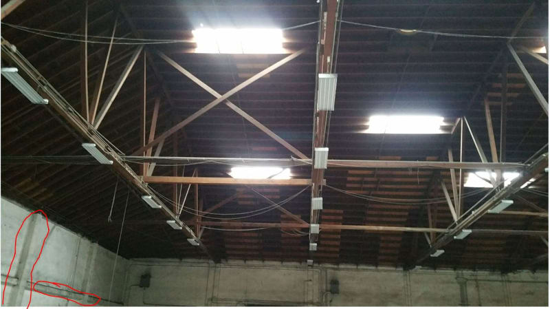
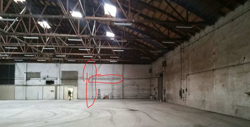
See the column and beam I circled red...

Why are there intermittent columns in the wall? There's only a continuous, uniform load from the rafters. This is an interior wall, the structure looks the same on the other side of this wall. I have a client who wants to cut a hole in the wall, cutting through a column and the beam.

The only thing I can think of is that they provide out of plane strength for the wall, so it doesn't have to span

Capture_jejcaa.jpg

Capture_oqfkyq.jpg

Capture_fdbtze.jpg
 
Replies continue below

Recommended for you

Its to break the wall up into justifiable masonry panels subject to internal wind loads. If you cut through them you need to stabilise the panel in some other way.
 
I've asked the Architect the same thing, CANPRO. Still waiting a response.

The panels would've been designed for a much higher wind load if they used to be exterior, and now would only need to be reevaluated using interior wind loads, and seismic acceleration, correct?
 
On the left side of your second picture it looks as if there's maybe a steel beam at the same elevation as the concrete beams in wall sections in question. Is that what that is? If so, could they be joints between precast panels? Could there be steel beams embedded in the beams and columns?
 
Both the column and beam protrude from the face of wall on either side of the wall - I don't think the wall used to be exterior. The building is enclosed, so the only wind pressure would be the minimum 5 psf, correct?

It seems that the beam and columns are only for out of plane seismic strength of the wall. Unless they could be to prevent shear buckling of the shear wall? I doubt it. They just seem so large for only wall out of plane seismic loads.

I'm trying to come up with some reinforcing (still preliminary, having calculated loads yet), and this is what I have. I know this would put the "beam" in torsion, so I might need to reinforce that. But IDK if i'm making a mountain out of a mole hill or what. If I could get any criticism on the reinforcing that'd be great. Thanks!

Capture_i8f7gk.jpg
 
- How thick is the existing wall?

- Do we know enough about the wall reinforcing that we could make a play for analyzing the wall with no reinforcing? Or are we stuck with a do no harm approach?

- I don't see the channel doing much of anything that the exiting girt thing couldn't do better.

- Any torsion headed for the beam will get drawn into bending in the wall above. So I wouldn't bother with torsional beam reinforcement.

- If the approach is "as good as it was", then I think that something is lost in the channels not being flexurally continuous with the column remnant above. That's probably what your thinking was with the beam torsion.

- A very simple solution if you can sell it might be to add a WF column either side of the opening that runs the full height of the wall. Place it outboard of the girt thing and tie back to the wall with some threaded rods for spacers.
 
Thanks KootK.

KootK said:
- How thick is the existing wall?

12", 22' tall. . The concrete column is 15" wide, 34" deep. (Protrudes past the wall 11" on either side). The column being so large is what's making me want to err on the side of safety and caution. Did the original designer see something I'm not? Just seems massive for out of plane wall support.

KootK said:
- Do we know enough about the wall reinforcing that we could make a play for analyzing the wall with no reinforcing? Or are we stuck with a do no harm approach?

No as-builts on this one. Doing a no harm approach.

KootK said:
- I don't see the channel doing much of anything that the exiting girt thing couldn't do better.

Yeah, I see that now. Something about reinforcing each side made me more comfortable at the time.

KootK said:
- Any torsion headed for the beam will get drawn into bending in the wall above. So I wouldn't bother with torsional beam reinforcement.

- If the approach is "as good as it was", then I think that something is lost in the channels not being flexurally continuous with the column remnant above. That's probably what your thinking was with the beam torsion.

Yeah that was my thinking. I was envisioning the wall as a "floor", with the column being a "girder" that picked up the beam. Cutting one half of the column off, and putting it's replacement transversely offset is relying on torsion in the beam to transfer the flexure.

KootK said:
- A very simple solution if you can sell it might be to add a WF column either side of the opening that runs the full height of the wall. Place it outboard of the girt thing and tie back to the wall with some threaded rods for spacers.

That's a good solution. I just feel weird not directly reinforcing the column.

I haven't been to the site yet (it's 1.5 hours away). Looking on google maps I might have made a realization as to why these columns are so large. I think that this interior wall might have been exterior as CANPRO stated. Exterior, AND previously supported an awning as shown below. This picture is of the exterior wall perpendicular to the interior wall I'm analyzing. The architect is visiting the site tomorrow, hopefully I'll get enough information out of him to make a judgement call.

Capture_t2rwon.jpg
 
I agree, the canopy explanation looks pretty promising. Ockam's razor and all. 12" seems like a thick wall to need all that stiffening, even at 22' height.
 
I have seen this type of wall construction in San Francisco. Also, for that same project, the adjacent buildings were constructed in stages over years from one end of the block to the other, so the exterior side walls became progressively interior. The common wall was used to support both roofs, and only three new walls were added for the second building onward.
 
Kootk said:
Ockam's razor and all

I think I learn as much from Googling your phrases as I do from the content you post! Your writing reminds me of Arthur Conan Doyle's.

moments said:
I have seen this type of wall construction in San Francisco. Also, for that same project, the adjacent buildings were constructed in stages over years from one end of the block to the other, so the exterior side walls became progressively interior. The common wall was used to support both roofs, and only three new walls were added for the second building onward.

Thanks. I feel comfortable assuming that this is the case with this building, but will still provide the channel reinforcing.

Thanks all for your input! And Happy Holidays.
 
cal91 said:
Your writing reminds me of Arthur Conan Doyle's.

I'm not familiar with his work but, now that you've made the comparison, I may have to check it out. Hopefully it makes me feel clever more than it makes me feel old. A happy holiday to you as well!
 
Well, now I feel like an ignoramus for not recognizing the author of Sherlock Holmes... I'm actually a voracious reader, I swear.
 
That system was fairly common in Florida with larger commercial building exterior walls (one-story), guessing before 1970 or so. The CMU is usually unreinforced, so the concrete "frame" is there for out-of-plane wind and seismic. That had to be an exterior wall as others have said.

Our approach would usually be sawcut the face of the CMU and add vertical reinforcing to your jambs and solid grout them. That concrete beam is probably fine spanning that but you don't have as-builts. I would move your channel up to the beam for a very conservative approach, gives you solid concrete to epoxy bolt into, and then sawcut and remove all of the CMU below that concrete. Fill in that space between the top of the door and the beam with metal stud or wood framing.

 
Status
Not open for further replies.
Back
Top