Continue to Site

Eng-Tips is the largest engineering community on the Internet

Intelligent Work Forums for Engineering Professionals

  • Congratulations IDS on being selected by the Eng-Tips community for having the most helpful posts in the forums last week. Way to Go!

What's the right connector

Status
Not open for further replies.

tgab

Civil/Environmental
Sep 14, 2020
8
Hello,

I’m struggling trying to model a connector. What I want is to give it specific elastic-plastic behaviors in the three motion directions regardless the rotations, so that if one end point is moved away from the other in direction 1, the connector activates its “1” elastic-plastic behavior, same for direction 2 and 3.
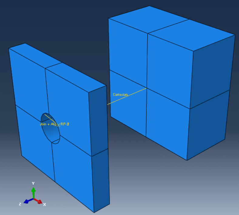
In my model, the first point is coupled to a surface of one 3D element and the other belongs to another 3D element’s face.
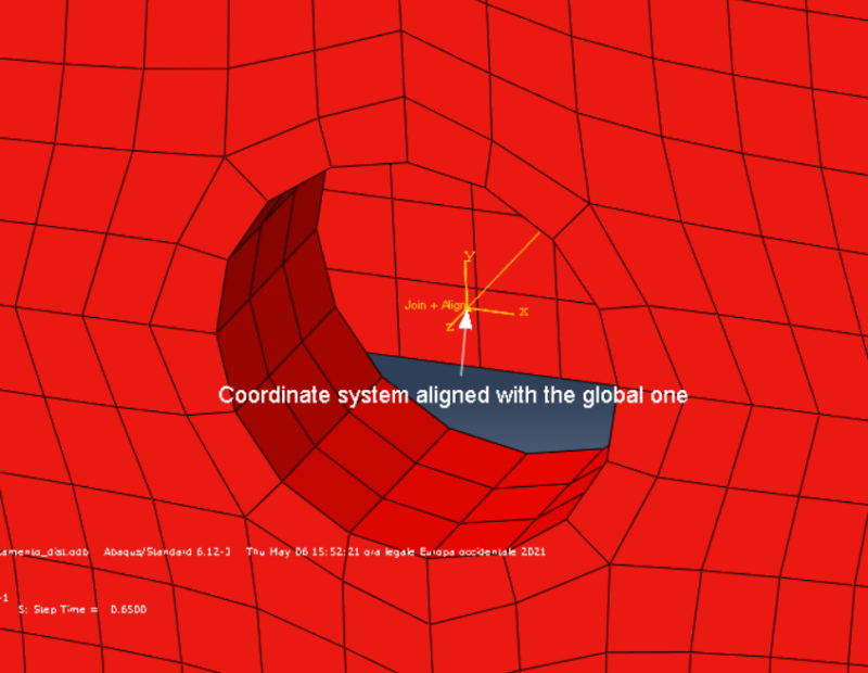
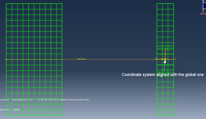
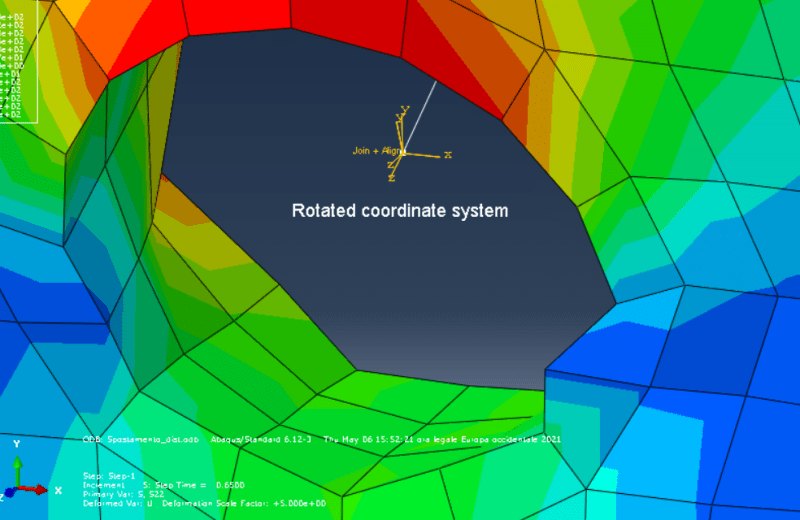
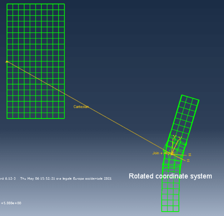
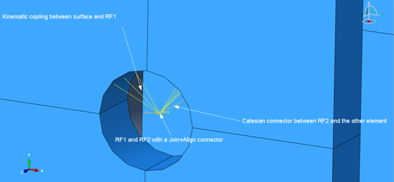
What I tried so far, after several attempts, is to create a reference point coupled to the first surface (RF1), then create a connector (join+align) linked to a second coincident point (RF2) that is the first point of the “real” connector, the one I am asking help for and that I modeled as Cartesian at the moment.
The problem I am facing is that when the second element moves, the coordinate system of the connector rotates with the connector, so the effective degree of freedom activated is the one along the connector, not the one in the direction of motion. I uploaded few images to help you understand what I wrote here. Thank you very much.
IMG1_inoi2w.png

IMG2_z8icsi.png

IMG3_uyo7aw.png

IMG4_yirpiu.png

IMG5_utoent.png

IMG6_ff7hfe.png
 
Replies continue below

Recommended for you

Does this model represent some real-life structure/mechanism or is it theoretical problem ? Cartesian connector seems like the right type here but I'm afraid that you can't avoid the rotation of conector's CSYS in geometrically nonlinear analyses. But you could experiment with different ways of attaching this main connector to solid bodies (maybe use rigid body constraint, coupling or MPC).
 
I might be wrong but can't you change the coordinate system that a connector uses? If that is the case then couldn't you set to use the global system instead of local?
 
Actually, in the case of Cartesian connector local directions for the first node are optional while for many other types of connectors they are required.
 
Thanks both of you!

FEA way:
The problem is a real life one: I'm trying to model a nail connecting a steel plate and a piece of wood, the two elements are detached at the moment because I just want to be sure of the connector behavior right now. When we test these specimens, we test their behavior in the three main directions and we end up with three different force-displacement behavior. I want to put those behaviors in my model, behaviors that only depend upon displacements and not on rotations, which should be free/not influence.

What do you mean with optional local directions? Maybe I lost it somewhere, but I didn’t find anything about the directions, they just appeared. I know other connectors need the coordinates to be set, I’ve tried the bushing connector in previous attempts, but I didn’t see anything like that in the cartesian, maybe I misunderstood your sentence, sorry for that.


DanStro:
Thanks for the suggestion and the interest in my post. As I wrote to FEA way, I didn't find anything like that for the cartesian, other connectors type I tried before had this specification to be made (bushing), but setting the global system or a different system not belonging to the connector didn’t give me any better result. Maybe I messed up a little bit, I don’t know, but this doesn’t seem to be THE solution. I’ll try again anyway, thanks.
 
During the connector section assignment, in the case of some types of connectors, you will get an error if you don't define local directions (orientations) and leave it with the default global CSYS. Other types of connectors (including Cartesian) don't require this definition of local directions.

For approximate modeling of nails and similar connections, mesh-independent fasteners are often used. But this approach might be too simplified for your purposes.
 
Thanks FEA way,
Yes it is, because I don't have a general pattern of fasteners, I need to place nails in specific positions and have them interacting with the holed plate, as the last step of these analyses would be to have the plate to be split in two, as happens during some tests. I need each connector to act as a separate entity
 
Status
Not open for further replies.

Part and Inventory Search

Sponsor