Eng-Tips is the largest engineering community on the Internet

Intelligent Work Forums for Engineering Professionals

When do you require Current Transformer in/out switches? 1

Status
Not open for further replies.

electrical429

Electrical
Nov 13, 2019
51
0
0
GB
Can someone please explain when do you need current transformer in/out switch the one shown on the image below.

CT_in_out_switch_rrvf4n.jpg


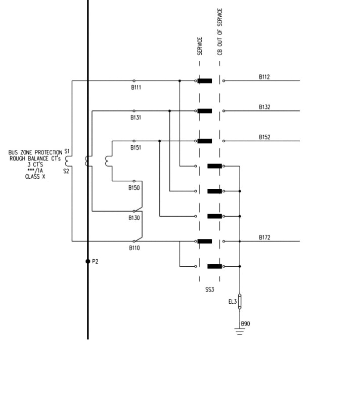
I have seen these on 132 kV high impedance differential protection schemes and 33 kV busbar protection schemes. I have also seen them on 132 kV transformer backup protection scheme. However I have also seen high impedance differential schemes and backup protection schemes without these CT switches. I understand that you can earth the CT using this switch and effectively remove the CT from differential protection scheme but why would you need it? For example imagine a busbar protection scheme shown below:

12-Complete-High-Impedance-Differential-Single-Line-r2_ajmpck.png


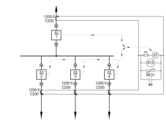
If you would install these CT switches on every current transformer in this scheme what would be the scenario when you would actually use them and for what purpose. My only though would be that if you need to do some testing works on differential relay itself then you would have to trip all the breakers. Then earth all the CTs. Then close all the breakers and commence differential scheme testing/maintenance while the substation is in service. And without these CT switches you can only do differential relay testing/maintenance while the site is out of service. Is that correct?
 
Replies continue below

Recommended for you

The switches would be used to test the relay. Test switches will short out the CT, open the circuit to the relay and provide a place to inject current into the relay.
 
But you could also do the same without using CT switches? i.e. you would short and earth CTs at CT terminals using wires and inject current into the relay there as well? So CT switches are just a more convenient way of doing this?
 
Yes, you could short and inject without test switches, but test switches make it a lot easier and less prone to error. Errors could include opening CT circuits under load resulting in high unsafe voltages and CT damage. Also tripping the station out. If you short one CT in the differential scheme and have current in the other CTs, you may cause a differential operation. Generally you would also include test switches to open relay outputs so that you don't trip things while testing the relay.
 
Often used with draw-out breakers and relays so that the CTs are automatically shorted when the equipment is drawn out to the test position or drawn out completely.

--------------------
Ohm's law
Not just a good idea;
It's the LAW!
 
Then earth all the CTs.
Should be;
Then short all the CTs.
CT circuits should be earthed to avoid the possibility of capacitively coupled high common mode voltages, among other reasons.
CTs should be shorted to avoid high open circuit voltages.

--------------------
Ohm's law
Not just a good idea;
It's the LAW!
 
If you are subject to any kind of regulation for testing, the test switches will pay for themselves during commissioning.

I recall 20 years ago testing relays for multiple generator locations that did not have test switches. At the time, I had an electrician by my side to remove and land wires on an 8 unit station. That kept the union happy.

Fast forward 15 years and I’m back to do simple maintenance testing of relays. Basically every wire that was lifted had to be treated as uncommissiomed. All of the retesting efforts when a simple test switch can be opened or closed quite easily.
 
Relays are often tested while equipment remains in service. If the backup relaying option can still clear any faults within acceptable criteria, no need to de-energize the whole site. In some cases to facility relay testing while energized, remote terminals may be temporarily configured with overly sensitive elements.

Without test switches, injecting test currents is complicated:
1) No existing wire terminations in the CT circuit can be modified until the CTs are shorted. Adding shorting wires usually requires lifting an existing wire to add new wire for shorting.
2)Luckily, the first terminal block after a CT usually includes the capability short the CT via temporary "shorting screws".
2a)Unfortunately, improper use of shorting screws has caused numerous protection failures. It is easy to incorrectly short the wrong CT, or to forget to unshort the CT at the completion of work. Usually test switches are all left in the "normal" state, so abnormal test switch position is obvious at a glance.
2b) Unfortunately, the shorting terminal blocks are often close to the CTs rather than the relays. In medium voltage applications, access to the shorting terminal blocks usually requires opening breaker cubicle doors. In high voltage applications, the shorting terminal blocks are mounted inside the PCB control cabinets, requiring a lengthy walk from the control house to the yard.
3) In order to inject currents into the relay, the wires between the relay and the temporary shorting location have to be lifted. If the relay was not isolated, any injected current could flow through the shorting wire/screw rather than the relay.
4)As others mentioned, each wire termination modification introduces possible mistakes. Possible mistakes include failing to retighten the connection to the proper torque, damaging the termination by repeated use, failing to reconnect all wires at the end of testing, or relanding the termination on the wrong terminal block. lifting or placing a wire
5) CT circuits must be grounded in exactly one location. If wires are lifted/added during testing, it is possible that the single point ground could either be inadvertently lifted, or than multiple grounds could be placed. Depending on exactly how shorting terminal blocks are configured, they can cause a second ground connection.
 
I have never seen that particular switch arrangement before, but it makes sense for any scheme where multiple CTs are paralleled into a single relay input. The most common is going to be a high-impedance bus differential. Moving the switch from Normal to Isolated would first apply the shorts and then remove the normal connection. While in the intermediate shorted but not isolated position, the whole bus diff would be ineffective since shorting any one of the CTs shorts them all, but as the switch moves into the isolated position it removes the short from the rest of the circuit. That's a lot more trouble-free than having someone change a bunch of wiring. Should only be operated after the breaker is in a clearance and no longer part of the bus diff.

I’ll see your silver lining and raise you two black clouds. - Protection Operations
 

What can we do after shorting CT. Bus differential will still be in service, we can not inject any current to it. For CT testing we have to open th CT anyway.
 
Thanks everyone. One last question. I have never seen CT in/out switch on a single CT set feeding one relay, only where multiple CTs are connected together, i.e. high impedance diff scheme, rough balance busbar protection scheme, transformer IDMT backup protection with two infeeds etc. If CT in/out switches are so convenient for testing/maintenance why aren't they fitted on all CTs as standard?
 
CT In/Out switches are not standard and in fact not recommended for the reason that there is a risk of CT open circuit while operating the switch.
Instead, the Test terminal blocks (TTBs) are more popular which allow relay testing without disturbing the CT secondary wiring.
Switching CT wiring was a necessity in high impedance Bus differential protection schemes associated with two bus switchyards. Whenever, a feeder is switched from one bus to the other, the corresponding busbar protection CT secondary wiring also needs to be shifted for bus bar protection to work correctly. There used to be CT switching relays that shift the CTs automatically based on the bus isolator status.
Now a days, clients with Two bus configuration switchyards prefer Low impedance busbar protection schemes with numerical relays that do the switching digitally internal to the relay making it safer (as there is no physical switching of CTs).
 
Status
Not open for further replies.
Back
Top