Eng-Tips is the largest engineering community on the Internet

Intelligent Work Forums for Engineering Professionals

  • Congratulations waross on being selected by the Eng-Tips community for having the most helpful posts in the forums last week. Way to Go!

Which free body is correct? 1

Status
Not open for further replies.

see_gen_notes

Civil/Environmental
Feb 4, 2016
17
US
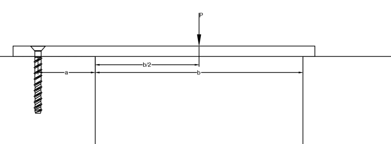
Screenshot_2024-04-01_115349_tuv3cr.png


I've been following some old calculations to determine the tension load on the anchor but now I'm second guessing on weather this is really right. Previously the tension load for image was determined based on the free body:
1) [Fixed] --- b --- [PIN]
where the moment was found and divided by ---a--- for the tension load​

Now what I think it should be is:
2) [PIN] --- a --- [ROLLER] --- b --- [ROLLER]
The tension load would be the reaction at the pin.​

Method 1 gives you a much smaller load while method 2 is larger. Which method to you makes more sense? Or is there another way I should look at it?


Edit: Method 1 actually did give me the larger load, I supiedly forgot to change units as I was doing the checks. I'm going with method 1 as it as more consevative and the loads are still managable.
 
Replies continue below

Recommended for you

Method 2 essentially incorporates PRYING into your analysis. It is more correct.


Strikeout because Kootk is correct and I am wrong. [flush]
 
That assumes that your fixture being fastened is stiff enough to generate a prying force on the anchor.
 
That's a good point that I never connected. So another question is would you consider the anchor as a pin for fix? A fix in case 2 would give me a much larger tension load and there would be a tension load and a moment which I'm not sure how to design the anchor for. Would the total load be tension reaction + moment/edge distance (---a---)? Even though there is some moment I conside it pin similar to a column that has 2 anchors.
 
Based on the two modelling approaches described, I would expect the first to yield the larger anchor tension.
 
@KootK you are correct. I forgot to convert the moment back into inches when I was divding the moment arm which was in inches.
 
Method 1 should be conservative, more so than Method 2. Method 2 may be either fairly accurate, or conservative, depending on the bending stiffness of the plate relative to the axial stiffness of the anchor. A small anchor with a significant length of the shaft free to stretch, anchoring a very stiff plate, would see very little stress. OTOH, a fairly stiff anchor, with minimal length of the shaft able to stretch, especially anchoring a relatively flexible plate, would approach the result from Method 2.
 

The title of this thread (Which free body is correct? ) ,

It depends on the stiffness of the beam , the distances a and b.

1 - The first approach , assumes fixed support at dist. a . In this case , the FEM at distance a will be Msupp= 3Pb/16 and the tension load on the anchor would be T=3Pb/(16a) ( assuming no prying action). This is upper limit value.

2- The second approach [PIN] --- a --- [ROLLER] --- b --- [ROLLER] ( the tension load is the reaction at the pin.) is more realistic. One can imagine that , the beam will deflect upward at span a and FEM will not develop at distance a.

If you want to perform hand calculation, you can use superposition and one method; remove support at distance b and find the tip deflection. Then apply a force which compensates the tip deflection . This will be reaction at distance b. Now the system will be determinate and apply equilibrium equations to find the tension at anchor.

He is like a man building a house, who dug deep and laid the foundation on the rock. And when the flood arose, the stream beat vehemently against that house, and could not shake it, for it was founded on the rock..

Luke 6:48

 
1) is conservative as the condition of the LH end can not be more than fixed. Now how you resolve this fixed end moment into a couple is is up for grabs.

M = Pa is the smallest couple, as you have the longest possible arm, and possibly the more realistic model.

In my experience the compression load is either a uniform distribution (which doubles P) or a triangular distribution (1.5P).

And then of course you have the practical aspect of preload, which could dominate the tension in the screw !

"Hoffen wir mal, dass alles gut geht !"
General Paulus, Nov 1942, outside Stalingrad after the launch of Operation Uranus.
 
Can I vote for "none of the above" and say in many situations I would consider this a simple span with the screw doing nothing?

I recognize compatibility of deflections and rotations means I am not technically accurate - I am just saying for many situations I would ignore the screw.

Especially since it appears the support is wood (because this is a lag screw), and the wood directly beside the gap will compress.

DaveAtkins
 
Or is that a concrete screw? If so, there is a lot more stiffness in the support and moment should probably be considered.

DaveAtkins
 
I was just thinking about the tension on the screw for designing it. For bending of the plate, I would agree with DaveAtkins; ignore the screw and assume a simple span condition for the plate.
 
I also agree with DaveAtkins for the design of the plate. And the design of the screw in many cases.

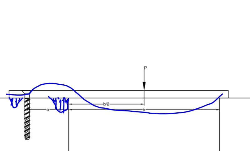
If the plate is thin enough to generate significant prying effects, that can actually get pretty complex. The reality is probably something like I've shown below.

c01_opgmag.jpg
 
@DaveAtkins it's a steel plate with concrete anchors. And I'd agree with you for small spans that the plate is stiff enough for a simply supported case. But for long spans I would detemine the tension load and settling with method I mentioned in the post (fix-pin and use the moment to find the tension).
 
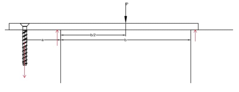
This is the FBD...

Clipboard01_vy1nrn.jpg


It's actually statically indeterminate, but for design purposes, I would consider it as a propped cantilever with a point load.

-----*****-----
So strange to see the singularity approaching while the entire planet is rapidly turning into a hellscape. -John Coates

-Dik
 
Status
Not open for further replies.

Part and Inventory Search

Sponsor

Back
Top