Continue to Site

Eng-Tips is the largest engineering community on the Internet

Intelligent Work Forums for Engineering Professionals

  • Congratulations IDS on being selected by the Eng-Tips community for having the most helpful posts in the forums last week. Way to Go!

Which kind of constraint to use between a wire beam and a solid element? 2

Status
Not open for further replies.

G_Barone

Structural
Mar 27, 2019
7
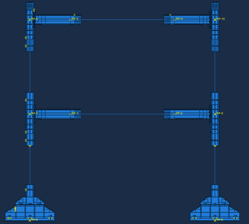
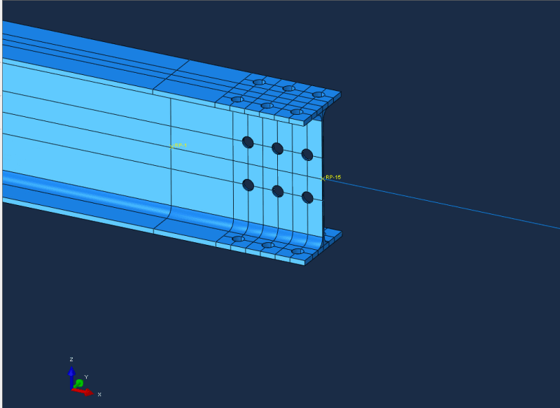
Hello everyone. I have some doubts about modelling in ABAQUS 6.14 a connection between a wire beam and a solid element (the other part of the beam, where I need to have a more accurate response):
Immagine_hoasxr.png

Which kind of constraint could I use? I was thinking to give a coupling between the face of the soild beam and the external point of the wire, but I don't know if that's the right choice. Thanks in advance.
 
Replies continue below

Recommended for you

You can use beam type MPC for this purpose. Just like in the cases when bolted connection is modeled as beam (representing bolt's shank) attached to selected faces of solid body. Coupling constraint should work too.
 
Thanks for the answer! So I should define an MPC (tie, for example) between the surface of the solid beam and a reference point, than linking that point to the end of the wire, with an MPC link?
In my previous test, I did a thing like this: I defined directly an MPC tie constraint between the solid beam and the end point of the wire, but the wire rotated rigidly around its end point (under an imposed displacement)... I can't attach a picture because I cancelled the output.
For the moment, I defined directly a coupling constraint between the end surface of the solid beam and the end point of the wire, without passing through reference points. I don't know if this is correct, but I would like to know more about your advice.
 
You can do it through reference points but I was rather thinking about direct connection between the surface of solid model and end of beam model. Either with MPC, type BEAM or kinematic coupling constraint. The second way should be easier to setup. Did you obtain the results with this approach (direct coupling) ? Do they look correct ? It's a good idea to try several methods and compare them to find out the best way. Especially that your model looks fairly simple and shouldn't take too long to solve. What are your boundary conditions by the way ?
 
As mentioned the rigid type of coupling is OK here so an rbe2 type or kinematic coupling, which will make the solid cross section there behave like the beam it is attached to. I would also suggest to place this further away from an area of interest. Assume now it is the hole area one can include too the right a small part. so mirror the left part relative the hole section part so to get it to the right of the hole part too, and then connect the beam Elements to that instead.
 
Thanks again for the answer, I set up the model with direct coupling constraint and this morning I just saw that the analysis aborted due to convergence problems.
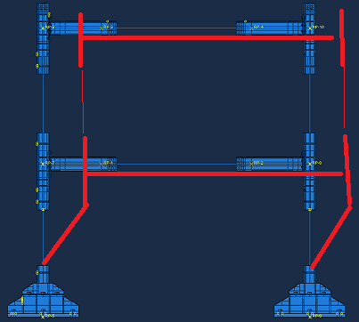
The part I evidenced in OP picture, is part of a 2D two-storey frame, so it's not a very simple model to run:

Immagine_i2ya55.png

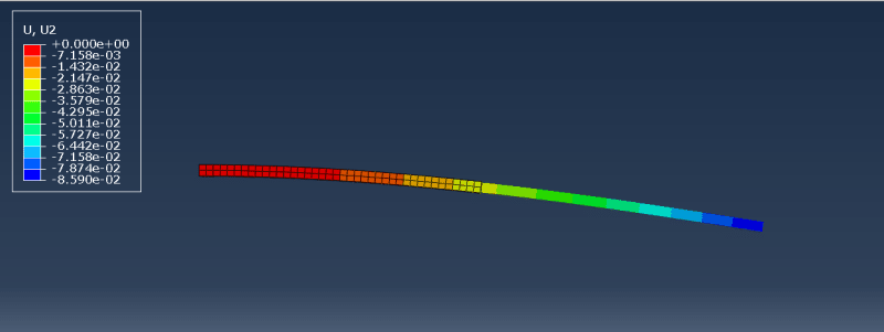
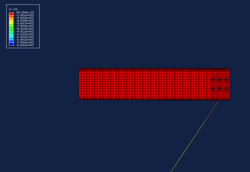
When I tried with MPC (tie type) connected directly between the various solid elements and respective beam elements, the analysis succesfully finished, but the displacement was definitely strange, because it was a thing like this:

Immagine_pqq4w4.png
 
Keep in mind that beam element’s nodes have rotational degrees of freedom unlike solid element’s nodes. This may cause problems.
MPC type BEAM might be better in this case.
However coupling should work too. Maybe the error is not in the connection. Did you try distributing coupling ? There’s an example with it in the Verification Manual. Check it if you’re not sure how to set it up correctly (search for „beam-to-solid coupling model”).
 
@Erik Panos Kostson so you're suggesting to use coupling but selecting the holes instead of the face of the solid element, right?

@FEA way I'm trying with MPC Beam type of connection. While the analysis is running, I'll give a look to the manual for "distributing coupling". Thanks for the help!
 
I think Erik meant to move coupling away from the holes (since they are stress concentrators) by adding another part of non-performated solid beam between perforated part and wire beam.

Make sure there are no errors for example with the wire beam cross-section. Visualize it in the Assembly module. Also check its properties.
 
See below - pardon my artistic skills but I think it should be clear (so do this if holes are the areas of interest where highest critical stresses would be expected, and you want to capture that)
From experience working with civil/struct. engineers if they do something detailed like this (which is not very often, since it is way to detailed - connection design is done in according to code by hand or in special software), rigid type of connections are used thus rbe2 and kinematic coupling for all 6 dof. In Strand 7 this is a rigid link cluster.

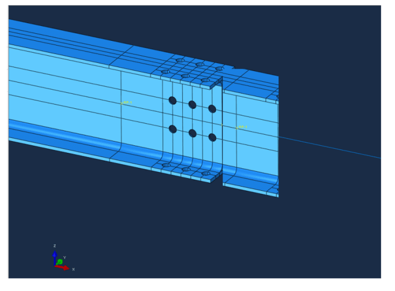
Capture_saxa41.png
 
An example where coupling of kinematic type (all dof used) and it behaves as expected (see below)

Capture_fccz9c.png


The m_Set-1 ref node is the vertex on the wire body (beam elements), and the s_Surf-1 is the surface on the 3D geometry (3D elements) where the beams connect to.

Example:
Code:
*Nset, nset=m_Set-1, instance=Part-2-1
 1,
*Elset, elset=_s_Surf-1_S2, internal, instance=Part-1-1, generate
 1,  4,  1
*Surface, type=ELEMENT, name=s_Surf-1
_s_Surf-1_S2, S2
** Constraint: Constraint-1
*Coupling, constraint name=Constraint-1, ref node=m_Set-1, surface=s_Surf-1
*Kinematic
 
Sorry for late replying to this post, but i was trying to test some options.

@Erik Panos Kostson I realized a smaller model (like yours): a simple solid beam and wire beam, with a vertical force at the end of the wire. For constraining solid and wire members I used:

1) Coupling Kinematic → Analysis aborted due to errors (too many attempts made for the first increment);
2) Coupling Continuum distributing → Successfully completed;
3) MPC Tie → Strange deformed shape:
Immagine_csy6qv.png

Of course something wrong
4) MPC Beam → Succesfully completed.

There are some small differences in terms of maximum displacement between 2) and 4). So, I'm going to try these two set ups on the planar frame. I noticed also that model with Coupling continuum distributing took more time to finish the analysis.
.
Anyway, could someone explain me why 1) and 3) gave me these results?
 
Is your analysis geometrically non-linear (NLGEOM=On) ?

Can you attach pictures or describe how you specified the nodes/sets to be connected with coupling and MPC constraints ? There might be an error in the way you choose regions for these interactions.
 
Status
Not open for further replies.

Part and Inventory Search

Sponsor