Eng-Tips is the largest engineering community on the Internet

Intelligent Work Forums for Engineering Professionals

Why is it OK per the NEC for feeders over 1000V to not have overcurrent protection at their rating? 1

Status
Not open for further replies.

bdn2004

Electrical
Jan 27, 2007
792
0
0
US
Article 240.101 in the National Electric code allows the overcurrent protection for feeder cables above their ampacity for feeders over 1000V.

240.101 Additional Requirements for Feeders (over 1000V)
(A)Rating or Setting of Overcurrent Protection Devices. The continuous ampere rating of a fuse shall not exceed three times the ampacity of the conductors. The long-time trip element setting of a breaker or the minimum trip setting of an electronically actuated fuse shall not exceed six times the ampacity of the conductor. For fire pumps, conductors shall be permitted to be protected for overcurrent in accordance with 695.4(B)(2).

I'm looking at the existing settings on 12kV feeders in this Plant, and many have the long term settings set around 700A on a 470A rated cable.

What's the logic behind this in the NEC ?

 
Replies continue below

Recommended for you

Typically medium voltage systems are managed better than low voltage systems and "overload" is less likely to occur. Low level faults can still occur and you don't want too much head room between load and fault. Once you get to utility systems you find that overload prevention is an operator task the protection system needs to stay out of the way and allow the operator to overload temporarily as needed.
 
Thanks....that makes sense. But is there any kind of rules of thumb - like 1.5 X ampacity of the cable should be the set point?
 
Nothing says you can't set it down at 100% of ampacity if you'd like. Analyze the situation, understand the likelihood of overloading, and set it as appropriate. The code allows room for temporary conditions that might not exist at lower voltages (cold load anybody?, inrush of lots of transformers, etc.) but you don't have to use it. It also gives you room while stacking relay curves on top of each other to maintain coordination and allow the lower levels to worry about overloads and the higher levels to deal with uncleared faults.
 
Generally, the maximum possible load is fairly easy to define at medium voltage - at least in the industrial world. Add up all of your transformer kVA ratings on the feeder and set the OC protection to pickup somewhere above that.
 
bnd2004 said:
But is there any kind of rules of thumb - like 1.5 X ampacity of the cable should be the set point?
As discussed, utilities set up to where smoking conductors and the occasional flaming transformer are acceptable. They are not bound by the NEC.

Us mortals on the customer side of the service are not only bound by the NEC. Generally our customers (industrial in my case) insist that the installation run WFO + 10%, 24/7. The utility solution is not acceptable. None of which addresses the question.

Personal opinion (which may not be any better than the next shoe clerk)
Art 240, part IX, is one of the few areas the NEC recognizes that installations such as Grandma's Abrams A-1 factory is not the same as Grandpa's cottage-by-the-sea. As david commented, the allowed 6X ampacity (for CBs) covers inrush. The OCP protects against short circuit, but not overload.

Finally - an answer. My rule of thumb:
When doing (or reviewing) the coordination,
Pay attention to the customers future needs. See the informational note following 90.1.B. The installation cost have to be kept down, but still don't hamstring the customer.
Overload protection is by design. Pick the cable ampacity to handle the load within normal temp specs.
Plot the cable damage curves. Set the OCP to trip inside of the cable damage curve.​

Art 240.101 (and art 240.100) are code limits - not good engineering.

carl

Harmless flakes working together can unleash an avalanche of destruction
 
What does WFO stand for?

At the Plant I'm working for...I'm looking at the existing settings - they appear to be set similar to what dpc stated in his post - slightly above the FLA of the connected transformers. What's interesting (or confusing) is that all of the feeder cables are the exact same cable: armored 3/C 500 kcmil, 133% shielded tray cable. But because of the varying loads on the feeder breakers - all of them set different. One is set for 385A the next 650A, etc.

And to confuse things even more - there's an Auto-coordinate, computer generated settings app that comes with software - and it recommends using the 6X times rule - The main on the Switchgear for example to be set at 7000A - even though it's a 3000A main breaker and bus. It appears it puts a premium value on the coordination between relays - not on overload of the circuit.

The method dpc suggested seems to be the most intuitive and easiest to defend.
 
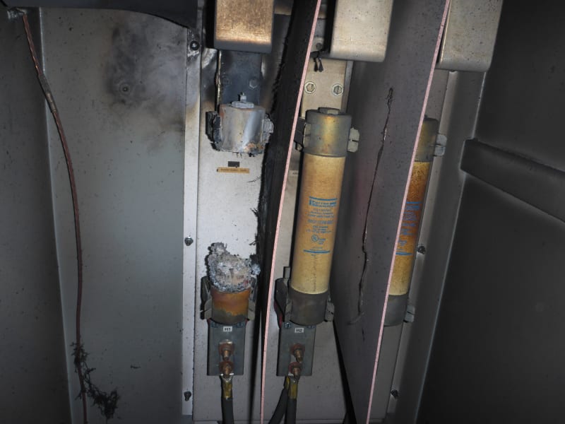
Lots of medium voltage fuses have a minimum opening current which means they will clear properly at higher short circuit currents but may not safely clear low level overload currents. So, this can mean using what seems to be a fairly oversized fuse which relies on a relay elsewhere to catch the low level overloads. Overloading certain medium voltage fuses a bit often doesn't end well for the fuse.

P1010355_w94hxb.jpg
 
You do have to consider transformer inrush in addition to max load current. This can tend to push fuse sizes a little larger. The S&C software is probably taking this into account.
 
The inrush is considered.

The E-rated fuses are at the transformers. They don't protect the transformer very well in the thermal range - as in the fuse curve is to the right of much of the thermal damage curve. But this was from the factory and is not being changed.

The feeder relay could provide better protection of the transformer(s) - but these are not radial feeds, ie one transformer fed from one feeder breaker. Each feeder breaker feeds up to 8 transformers on the same circuit.

I've been trying to come up with a logical, straightforward philosophy how all the relays are set. And all set the same way.
 
Fuses generally don't provide full range protection against the ANSI transformer damage curves, especially for ground faults on delta-wye transformers.
 
Status
Not open for further replies.
Back
Top