Continue to Site

Eng-Tips is the largest engineering community on the Internet

Intelligent Work Forums for Engineering Professionals

  • Congratulations KootK on being selected by the Eng-Tips community for having the most helpful posts in the forums last week. Way to Go!

Why is one mechanism more prone to jamming? 4

Status
Not open for further replies.

Jonahtang

Mechanical
May 9, 2022
5
Let's say i'm designing a rectangular button with these two different cross sections. The button is constrained on the left and right by a vertical wall and supported on the bottom by a spring directly below the CG. The only difference between options 1 and 2 is length l.


Three questions:

1. If a force is applied off center, why is option 2 more prone to "jamming"?

2. Why can be done geometrically to reduce likelihood of jamming?

3. What if the button was a cylinder instead of a rectangle, would that help and if so, why?

[URL unfurl="true"]https://res.cloudinary.com/engineering-com/image/upload/v1652147076/tips/IMG_2919_brvepq.heic[/url]
 
Replies continue below

Recommended for you

add some guide rails on the inside of the receptacle, and grooves on the outer faces of the button, to encourage the button to translate.

it should be obvious why the wider button would be more inclined to jam, to "cock" in the receptacle (because the push force can more easily not be aligned with the spring)

another day in paradise, or is paradise one day closer ?
 
Hello,

This bears some resemblance to the "binding ratio" encountered with plain bearings (i.e. bronze bushings). A typical rule of thumbs is the "2:1" ratio that relates the distance between bearings.

Here is a link to an article discussing the topic:


Another example is the magazine follower in AR15/M4 type rifles. They are advertised as "anti-tilt" to address an issue similar to yours.

Kyle
 
Thank you for explaining about the chamfers - understood now. It takes more into account real materials that would squish a little and dig into each other instead of this perfectly rigid parts in theory.

kjoiner said:
This bears some resemblance to the "binding ratio" encountered with plain bearings (i.e. bronze bushings). A typical rule of thumbs is the "2:1" ratio that relates the distance between bearings.

Here is a link to an article discussing the topic:


This link you provided is gold! Really helped me understand this.

rb1957 said:
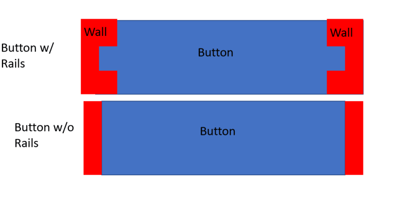
add some guide rails on the inside of the receptacle, and grooves on the outer faces of the button, to encourage the button to translate.
I don't understand why these guides would help. From a top view, is this what you mean? I don't get how the rails would be better than a button of the same width, can you please explain?
Button_Rails_rgpmkx.png
 
Three comments on the formula BrianE22 gives in his 10May22@19:07 post.

(1)[ ] It is easily derived, and seems "sensible".

(2)[ ] It strongly suggests that chamfers and radii are NOT a good idea, because they reduce the effective L. They may well be a good idea for smooth operation, but they should be kept as small as possible.

(3)[ ] The approach can easily be extended to allow for the fact that there will usually be some clearance between D (the diameter of the "bore") and W (the diameter of the cylindrical button of length L).[ ] The result is that you require
(L[sup]2[/sup] + W[sup]2[/sup])*cos[sup]2[/sup]f > D[sup]2[/sup]
to avoid jamming.
In this, f is the friction angle (=arctan(friction coefficient)).
 
Denial said:
It strongly suggests that chamfers and radii are NOT a good idea, because they reduce the effective L
If L is sufficiently long, chamfer will usually be only a small fraction of L, so it will not reduce L to any significant degree, but it will significantly reduce the effects of sharp corners that have been mentioned in earlier posts.
In other words, you gain much more than you lose in a properly designed hole-slider interface.
 
Many buttons have a cylindrical post in the center to reduce binding. In the images the guides would be added to the centers of the top and bottom (wide) faces to reduce the chance of binding.
 
A 15° chamfer is way better than a 45° chamfer for assembly etc.
"Broken" corners/edges/transitions are required of course.


A little more complicated "cam ground" button approaching/approximating 3DDave's radiused profile might not be necessary.

Counterboring the button on the spring side might allow lengthening the button to a more L/D ratio. 2/1 is a decent starting point.

How is the eccentric load occuring?
Would machining a plateau .5D in the middle keep the load from being applied so eccentrically?
Kind of like the inverse of this?
 
Status
Not open for further replies.

Part and Inventory Search

Sponsor