Continue to Site

Eng-Tips is the largest engineering community on the Internet

Intelligent Work Forums for Engineering Professionals

  • Congratulations KootK on being selected by the Eng-Tips community for having the most helpful posts in the forums last week. Way to Go!

Why isn't continuity of moment around a rigid joint fulfilled under a buckled shape?

Status
Not open for further replies.

fracture_point

Structural
Mar 7, 2019
58
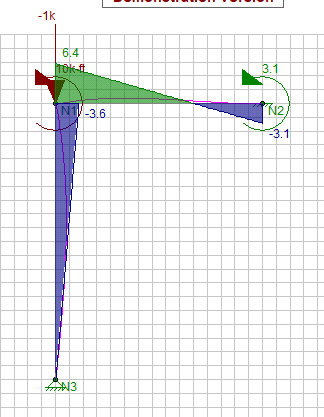
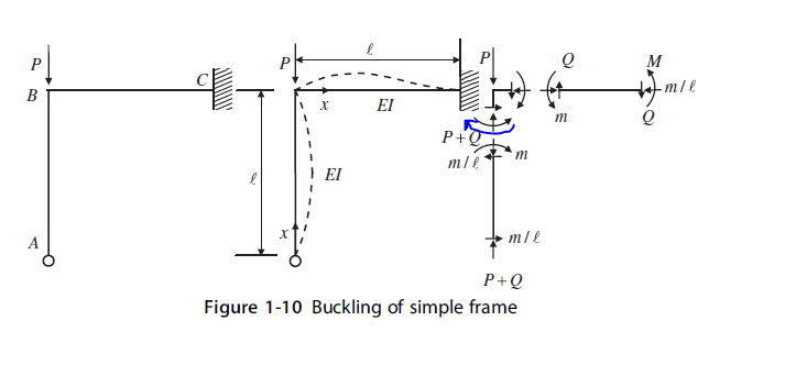
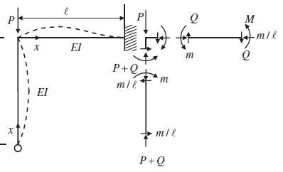
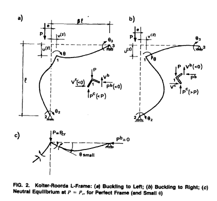
I'm studying from Stability of Structures by Yoo and Lee, and the example is deriving the buckling capacity of a simple frame. In the freebody diagram, there isn't moment continuity around the rigid corner. That is, there's tension on the right side of the column member at the corner, but tension on the top of the beam element (as opposed to the bottom). Can anyone provide a rationalization as to why moment continuity isn't necessary under a buckled configuration?

 
 https://files.engineering.com/getfile.aspx?folder=b197acaf-9ed8-41a2-8608-0c4b6f61fe18&file=a.PNG
Replies continue below

Recommended for you

I don't know the content of their work, but the diagram seems odd. See the diagram below (note the moment is drawn on tension side).

image_hddxbw.png
 
I don't know the context, but if the joint has buckled, maybe the stiffness approaches 0.

Rather than think climate change and the corona virus as science, think of it as the wrath of God. Feel any better?

-Dik
 
The tension is on the left of the column in the free body diagram.

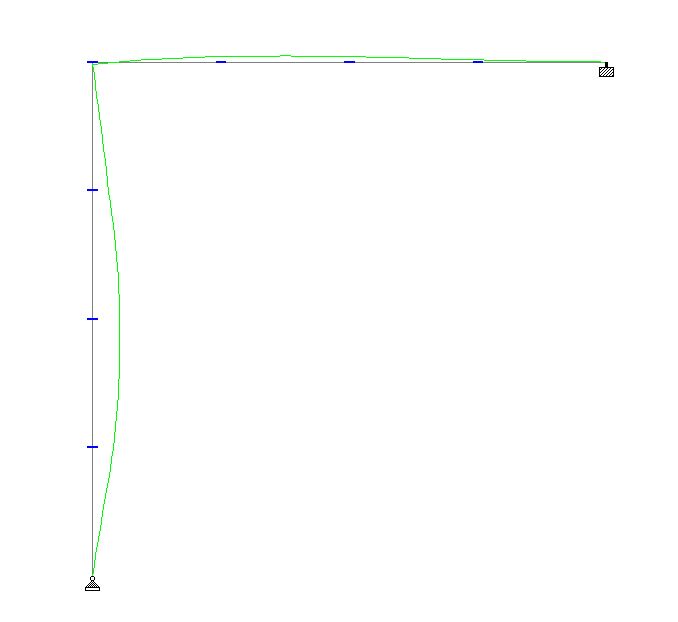
Here's the buckling shape from computer analysis:
Buckling_small_scale_hrhh5j.jpg


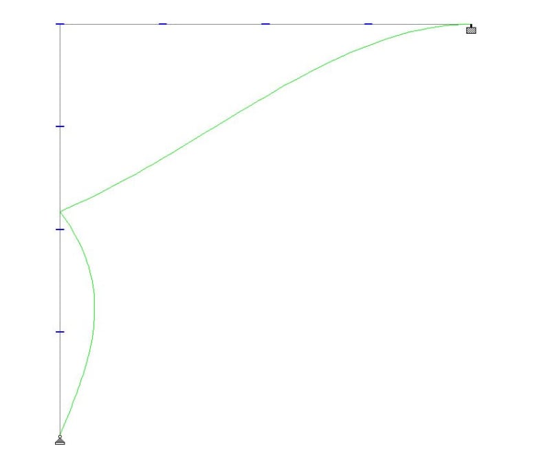
Here's the displaced shape:
Displacement_large_scale_soipjv.jpg
 
r13 - The moment diagram you have is from statics of an undeformed shape, as opposed to considering the buckled configuration. Your moments around the rigid joint do not need to be equal and causing tension on the same side because they are balanced by the external moment you have applied.

dik - if this were the case, it would violate the effective length method where we rely on rotational stiffness of connecting adjacent members to restrain buckling.

steveh49 - I ran a buckling analysis in ETABS and here are my results:

b_dzlbfx.png


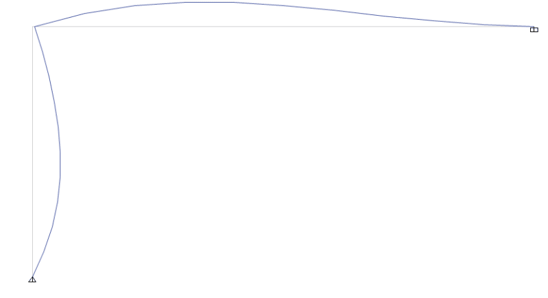
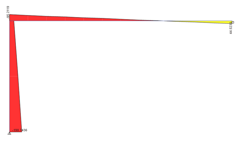
And here is the moment diagram:

c_isvtvd.png


This moment diagram clearly doesn't obey the typical statics rules, i.e. there is not continuity of the moment around the rigid joint, and there is moment developed at a pinned joint.

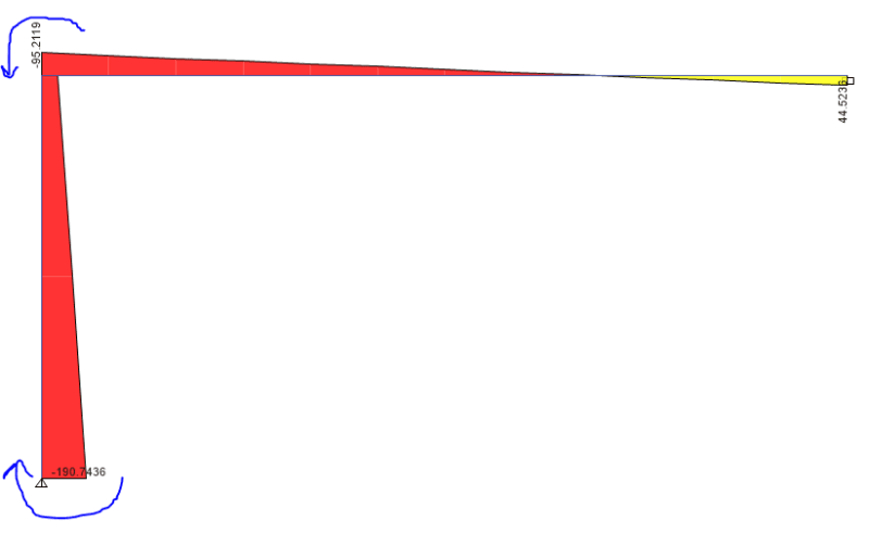
The only rational explanation to me is that the buckling of a column under compression load only is akin to taking an undeformed member and applying a moment at each end:

d_wa8kje.png


This would then satisfy the fact that there is not tension on the same sides of the beam/column at the joint and the moment at the pin connection. What do you guys think?
 
My only concern is that my above point would contradict the freebody diagram drawn by the author here:

e_ljpjba.png
 
r13 said:
I don't know the content of their work...

It's a classic, and fascinating elastic post-buckling problem. Google the Koiter Roorda Frame.

@fracture point: how many segments have you broken the member into? See steveh49's model.
 
@OP: also, what is the value of your axial load at buckling and what are the units of the moments? The crux of the example is sort of that it takes a perturbation to make the column choose one buckling direction over the other. It may be that the nature of that perturbation is what's generating the unexpected results. That, if the results are small relative to the applied load.
 
I think you're just not looking at the problem correctly. I think it still obeys statics. However, it might only obey statics under large deflection theory.

As such, you need to remember to consider the following:
a) End moments of each member (including their local axes, sign of the moment and which side of the infinitesimal element the moment is acting on).
b) Any loads applied to the structure.
c) Deflection and how the program accounts for it in the analysi. Do joint loads move with the node as it deflects and such? Is the solution an iterative non linear solution where a small portion of the load is applied to the undeflected structure, then the stiffness matrix changes and the next increment is applied to the deformed structure? Are there internal forces added to the structure to account for the deflection (P-Delta secondary forces)? Etc.
 
@fracture point,

You can't have a moment at a pin support. Something is wrong there.

Also, what is your sign convention for moments? If it is clockwise positive, then a negative moment top and bottom would mean there must be an inflection point between.

BA
 
fracture_point said:
r13 - The moment diagram you have is from statics of an undeformed shape, as opposed to considering the buckled configuration.

The externally applied moment in my analysis is to produce the effect of column buckling - bowing. As you can see that there is no joint translation in the figure provided.

image_mbx1ot.png
 
Part of the issue is that you may be trying to compare the first order moment diagram to the buckled shape. I get a different moment diagram when I run a second order analysis taking into account the curvature of the buckled shape. And the diagram above appears wrong with the moment at the pinned end.
 
From KtooK suggested search, I found an ASCE paper that contains the graph below. Note the difference on the left support. The paper is linked here. Link

image_hkmo6b.png
 
Theres something odd about your analysis for sure. Maybe try replicate the buckling result in another program.

Do you have a moment applied at the moment joint, that might explain the odd moment diagram.

I'm not sure if the moment diagram from etabs is that relevant as you are simply working out the critical axial buckling load under an applied axial load, is etabs even capable of doing a flexural torsional buckling analysis (i.e. inelastic/elastic buckling under moment?). applied moment does not affect the determination of the effective axial buckling length (i.e. consider eulers equation P_crit=pi^2EI/(kL^2))

The moment doesn't really factor into it, yes its a by-product of the fact that it buckled under axial load that some moment will be generated as it collapses. But it's a little irrelevant isn't it, because it occurs after it has buckled?

It's not like you're taking your moment and axial load from this analysis and checking the member(s) for this, the member buckled, it failed, end of story.... all you can extract is the critical axial buckling load, which then feeds into your critical buckling stress which can be used directly with your codes column buckling curves to account for second order effects (residual stresses, member imperfections, etc).

[never done a buckling analysis in etabs so not familiar with the output it spits out, or even what type of buckling analysis it is actually capable of doing]
 
Status
Not open for further replies.

Part and Inventory Search

Sponsor