Continue to Site

Eng-Tips is the largest engineering community on the Internet

Intelligent Work Forums for Engineering Professionals

  • Congratulations GregLocock on being selected by the Eng-Tips community for having the most helpful posts in the forums last week. Way to Go!

Why no tolerance on bearing ID/OD? 3

Status
Not open for further replies.

tinnguyen123

Mechanical
Feb 11, 2016
11
Hello,

I been trying to design my shaft for a bearing that meet the specs.. However, the manufacture usually only give a nominal size..

Then I went and look for others.. and they all seems to only give a nominal size..

is there a reason to that?
 
Replies continue below

Recommended for you

You're not looking in the right areas or in the right documents. All bearing manufacturers will tell you the tolerances for the housings and the shafts.
 
I believe the OP is asking for tolerances on the bearing dimensions, not on the shaft and housing fits. I entered "ball bearing dimensional tolerance" into a search engine. One of the first hits was the SKF page with dimensional tolerances for thier bearings.


Johnny Pellin
 
The link ( ) has the bearing tolerances, and more important, the various ISO fit classes/grades.

Most of us Humans are not born knowing when a bearing race should be a slip fit or heavy interference, nor the tolerance on journal roundness, surface finish, journal fillet radius or shoulder height.
Knowing the actual bearing dimensional tolerances are generally not part of the calculation.
Selecting the proper shaft and housing fit class ( g6, H7, etc) based on application is really the only step necessary. Then those tolerances are applied to the nominal bearing diameters to dimension the shaft and housing.

Knowing the actual bearing dimensional tolerances are generally not part of the calculation.
Table 7.6(1) and (2) list the bearing ring ID and OD tolerance (∆dmp, ∆Dmp) in the first column. The other columns contain the values for tolerancing the housing bore and shaft journal seat diameters for over 2 dozen ISO fit classes/grades.

Figure 7.1 is a nice graphical representation of both bearing tolerances AND the shaft and housing tolerance of the various ISO fit classes/grades.

One exception might be designs that clamp a race axially. Then the bearing's widths, and its tolerance would have to be considered and understood.
 
Tmoose said:
Knowing the actual bearing dimensional tolerances are generally not part of the calculation.
Selecting the proper shaft and housing fit class ( g6, H7, etc) based on application is really the only step necessary. Then those tolerances are applied to the nominal bearing diameters to dimension the shaft and housing.

This was what I was expecting... because not many vendor provide bearing ID/OD tolerances. I never heard of ntnamerica, feel ashamed.

Another question, if anyone mind answering. I know larger bearing/heavy machinery usually require tight fits. Can I get away with going under sizing the shaft for slip fit and use a eccentric collars to lock the shaft in place?

 
I would add that it is not uncommon for companies to use slip fits when it is necessary for assembly or some other reason.

Generally it is best to have a way to hold the inner ring (for example) axially in preload with a nut, clip, etc.

Sometimes it works. It just depends on the application. Are you aware of anything else we should know- a lot of start/ stop, speed changes, high inertial loads, odd materials (al housing), shock loads, vibration, temp changes, etc that might influence the fit?

At a minimum you should always start tight on the rotating ring (see the tables referenced above) and work from there.

 
You guys are really scaring me.

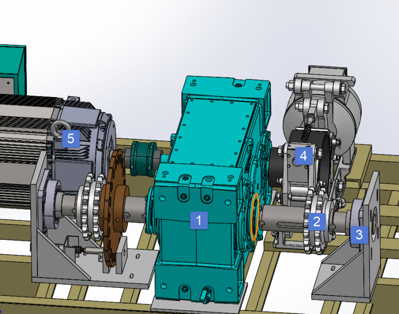
2016-12-06_7-13-13_ay6txo.jpg


1) Gearbox
2) Sprocket
3) Pillow Block
4) Brake for the motor
5) Motor

The shaft is 4-3/8" Dia. All of this is to move a 10,000 LB concrete block(counter weight) up and down.. it'll moving about 20-30 RPM (Low RPM).. The bearing is rated for 22,900 Dynamic Load or 17,600 Static Load .

The output shaft will be slip-fit, held down with the collars (Item 1,2 & 3)

On the input shaft side, everything is interference fit. (Item 5,1 $ 4)
 
The AST bearing link is to a bearing for a fairly whopping 3.5" nominal shaft Ø .
Is that the size of your machine?

Better get all your info to the bearing application engineers up front. There are a bunch of details to consider. Thermal expansion, shaft critical speeds,etc and etc.

(And if this mystery device is belt driven, I'd STILL avoid setscrews and eccentric locking collars !! unless the shaft to bearing fit is line-to-line or interference, which like Fugeguy said, the assembly team is going to hate )
 
yes it is a 3.5" nominal, just to fit the bearing.. if you look, that output shaft is a step-down shaft from a 4-7/16, to a 4-3/8, to 3.5.. I couldn't find any pillow block bearing larger than 3.5..

We already did a lot of calculation and this size should be more than adequate.. I'm just not sure about the fit on bearings..

Out of curiosity, how would you interference fit the pillow block into the 3.5 shaft..? Liquid nitrogen the shaft, and quickly put it in the pillow block? and once it's on.. how would you adjust it? Tubing & hammer?

To be honest, before this project, I didn't know shafts can get to that size, but then again, I think giant boats uses shafts much larger than this size..
 
Is the output shaft of the gearbox one piece and long, and integral with the gearbox?
Or, is the gearbox shaft hollow, and your shaft is 1 piece, reaching from flange bearing to flange bearing?
Are both sprockets lifting the load?

Taper bore bearings, with tapered sleeve adapters may be your best bet.
They Not the easiest to install correctly, but are very capable of gripping a well made shaft reliably in the presence of troublesome radial (and axial) loads.


Have the bearing tech folks blessed your arrangement in regards to rpm, ambient temperature, what rotates and what is stationary, the direction and nature of service loads, etc.
Before creating CAD models ALL that info, and more, needs to be processed and well understood.

If the gearbox has a hollow shaft, I'd be asking the gearbox manufacturers SPECIFICALLY about the fits required to keep your shaft and their hollow shaft from fretting each other horribly. I think a tapered sleeve is required on each end there too.

The sprockets slip fitted to the shaft will require the same attention to fit or they will tend to fret badly as well. Or benefit from taper sleeve mounting.

The output shaft will need to be very straight, and run very true, and the flange bearings will need to be nicely aligned to it and held VERY reliably.

There is no scale to the model, but the triangular bearing supports and square (tube) floor beams may let things move out of line when the load is applied. Four bearings in a row on the same shaft is NOT a trivial situation. If the structure is real stiff, and the shaft has runout or the bearings are out of line, the four bearings are going to get in a big fight with each other, to the detriment of the shaft and bearing life, and security of bearing mounting remaining tight . If the outboard structures are not nearly stiff enough, then the gearbox bearings will handle all the load, and the shaft will bow, similar to what would happen if there were NO outboard bearings.

To ensure load sharing, and increase the tolerance for misalignment, a radially stiff coupling could be used close to the gearbox on each side.
I'm thinking a single element disk or perhaps a single element gear coupling would work.
Page 28 here -
 
Status
Not open for further replies.

Part and Inventory Search

Sponsor