Continue to Site

Eng-Tips is the largest engineering community on the Internet

Intelligent Work Forums for Engineering Professionals

  • Congratulations KootK on being selected by the Eng-Tips community for having the most helpful posts in the forums last week. Way to Go!

Why not using a Synchronous Machine as a Dynamometer? 2

Shamooooot

Electrical
Oct 24, 2024
12
Hello guys

I am planning to make an AC dynamometer for research purposes to test PSA 4-cylinder diesel engines with the following specifications:
- Power max.: 60KW.
- Torque max.: 220 N.m.
- Speed max.: 4500rpm speed.
* Can't use the grid.
* Going to use dynamic torque sensor to log power, speed, and torque.

I thought of the induction motor option, but quickly changed my mind after seeing the added cost of the VFD with regenerative braking and the braking resistor.

I am now thinking of using a synchronous machine, which could indeed save me a lot of troubles, especially that I need less than 100VDC and couple of amps to control it and it would only need a load bank.. but after reading in the forum and in other places it doesn't seem to be a popular option in dyno applications. I wonder why is that and if I am missing something in such setup.

It seems to be hard to find synchronous motors that have such high speeds, and motors at that power and torque seems to be too expensive, I believe a 3600rpm rated motor can survive 4000-4500rpm. And as this won't be used as an actual generator or tied to the grid and the power would be dissipated to the load bank the job doesn't look complicated. Especially, that these motors are fairly common and could be found at a good price.

I understand that an eddy current may be the best and safest option for the job, but I am required to use an "AC dynamometer".

Thanks in advance..
 
Replies continue below

Recommended for you

If you mean using a sync motor as a load; yes, that can be done. I used to do that all the time in my test lab. I used servomotors for this since the company I worked made servomotors we had lots of extras.

Connect the motor leads to a 3 phase variac, take the output of the variac to the resistive load connected in a wye. You can now dial in the load you want.

You can get a 2 pole motor to go to 4000RPMs like this. The issue is heat. You may have to put a fan on the motor.
 
I think sync motors were made for 400Hz systems, as well as 60Hz, so you might be able to find one with a higher speed rating. My recollection is 400Hz is used in aircraft to make things smaller.
 
Hmm. General statement is that the "off-the shelf" machine is mechanically designed to handle either 20 or 25% above top nameplate speed without coming apart and injuring someone. The limit is dependent on the governing design standards (IEC = 20%, NEMA = 25%).

What this means is that there is some room for an overspeed trip setting (typically in the 105-110% speed range) so that it will SAFELY trigger the shutdown process and bring the machine to a stop WITHOUT exceeding the 120 (or 125) percent limitation. Remember that a machine continues to speed up because of the built in time delays (i.e. detect the overspeed condition, send the trip signal to the control, have the control initiate a shutdown sequence, and have the sequence run its course to bring the machine to a stop).

If you're already operating at 4000 rpm, you're at 111% of rated speed - which means you time available to trip and shut down safely is already reduced significantly. At 4500 rpm, you've used up all the mechanical safety in the rotor construction (3600 * 1.25 - 4500).

Converting energy to motion for more than half a century
 
400 Hz sounds appealing, but higher frequency may mean more poles, not more RPM.
Start looking for a suitable reduction gear.
At 2:1 reduction you have a wide range of new and used/surplus machines available.
A 60 kW Variac to control the loading will be very expensive and may not be available.
Consider a direct connection to the load bank and control the output by varying the excitation.
A surplus automotive transmission may be an economical solution to speed reduction.

--------------------
Ohm's law
Not just a good idea;
It's the LAW!
 
Thank you guys, it is relieving to know that it can be done.

As waross said I thought I would just connect the sync machine to the load bank directly. I can control the load bank with about 1KW steps, and I can control the excitation current.

I am more worried about the control unit now, I read that this setup might be dangerous (changing load and/or excitation current) as it might make the generator lose synchronism which might be detrimental and might destroy completely destroy the generator.

Or am I wrong as I hope and it's simpler than that?
 
Losing sync is an issue when systems are running in parallel.
With a single machine connected to s load bank there is no synchronism to lose.

--------------------
Ohm's law
Not just a good idea;
It's the LAW!
 
Induction motors in that power range are relatively tolerant of overspeed. I think you'd have a hard time finding one with a 3600 rpm rating that wouldn't tolerate 4500 rpm. Synchronous machines, on the other hand, have wound rotor construction and are sensitive to throwing the copper windings off the rotor when oversped.

An automatic voltage regulator may have some issues with the higher speed. Maybe consider using your load bank's highest setting only and using a variable output constant current DC power supply to vary the load. A generator that size will likely have a 50 ohm field and need 3-10 amps to achieve rated voltage/power so you'll need 20-50 volts.
 
Thank you again.

TugboatEng
I see now that I need either an AVR or a fixed 60KW load bank with a DC power supply. Did you mean a constant current or a constant voltage DC power supply?.

This is needed because the "Voltage drops significantly with increasing load due to armature reaction and internal voltage drops".

If I used an AVR I would lose the control over excitation current and this won't have a significant effect on the dyno.
If I used fixed load bank, I would lose the load changing option and won't be able to control real power and torque.

This AVR costs about $500 Link
 
You are overthinking this.
1. Use gear reduction to get the speed down to whatever your generator will withstand.
2. Control the exciter with a DC supply capable of 0 to about 100 Volts.

That will be your basic dynamometer for fixed speed..
As you increase the voltage to the exciter field, the voltage will increase and the load current and the kW load will increase.
If you want automatic fixed loading as the test motor speed changes, that is another issue.
 
I believe a constant current power supply will provide better control but either type of supply will work.
 
I would like to make some
You are overthinking this.
1. Use gear reduction to get the speed down to whatever your generator will withstand.
2. Control the exciter with a DC supply capable of 0 to about 100 Volts.

That will be your basic dynamometer for fixed speed..
As you increase the voltage to the exciter field, the voltage will increase and the load current and the kW load will increase.
If you want automatic fixed loading as the test motor speed changes, that is another issue.
It was intimidating for me ngl, because I've never worked with such high power (for me at least) application so I don't want to face any surprises.

The tests to be carried are:
Speed Control: Constant Speed, rpm increase/decrease, RPM sweep at constant load.
Torque Control: Constant Torque, load increase/decrease, torque sweep at constant RPM.

So there might be an issue with the "automatic fixed loading" as it will require a control loop to adjust the excitation voltage to maintain a constant load.

Now as TugboatEng said there won't be a need for a variable load, can I just use a fixed 60KW rated load?.

I really appreciate all the help and I am thankful for helping me understand it better.
 
I'm having a hard time believing you'll find a used 3600rpm, 60kW brush type synchronous motor. You'll have to purchase a new one.

I have a hard time believing a manufacturer would give the OK for running a 3600rpm rated synchronous motor at 4500rpm.

By the time you put together a gearbox, 1800rpm motor, load bank and a field controller you're probably not saving the money you're expecting to save. At that point, you'd be far better served by requiring a grid connection and using a regenerative capable controller and motor, like a VFD and an induction or BLDC motor.
 
Wow this reply came in the right time, I actually went for a hunt locally for an induction motor and a VFD, and I did find a surplus that are really affordable.. I also did more digging and I found research someone did about almost exactly the same as I need.. and I would like to confirm what I ended up with, with you guys:

Engine:
Max. Power: 55kW
Top Speed: 4000rpm
Max. Torque: 185Nm
Speed at max. Torque: 1500rpm

Induction motor:
- 1500rpm rated speed, for minimizing slip and maximizing stable power output, and as the rotor speed need to exceed the synchronous speed to enter negative slip so the motor absorbs power.
- 29.06kW Power, P=T×ω, and current will be 56.7A (Voltage: 400 V, frequency: 50Hz, Power Factor: 0.85, Efficiency: 0.90).

Motor: 4-pole, 30kW or more, 1500rpm, 190nm or more.
VFD: 30kW but should have a flying start, and sensorless Vector Control options.
Braking resistor: 8Ω and 30kW rated, assuming duty cycle is going to be 100%.

Are these assumptions valid, or am I mistaken?!
Would it be dangerous to drive the motor at its full speed 4000rpm?
 
I agree that a 60 kW synchronous motor will be almost impossible to find.
However, rather than use a motor as a generator, how about using a gear box reduction and a synchronous generator?
There are lots of generators, new and used, in the 60 kW to100kW range.

This is a case where a PMG generator may not be a good idea, however you may ignore any PMG and use a mains powered power supply for the excitation of the integral exciter.
Automatic constant torque at varying speeds will be easy.
Automatic constant HP at varying speeds will be more difficult.
You may use the AVR for control within the safe frequency limits of the AVR.
You will have to disable the "Under Frequency Roll Off" feature of the AVR.
You will be limited to the lowest safe frequency of the AVR.
Operating at too low a frequency will destroy the AVR.
The UFRO protects the AVR from low frequency.
With UFRO disabled. you will need some other way to avoid low frequency operation.
 
I wouldn't expect a 1500rpm motor to operate at 4000rpm.

Find a 3000rpm motor that is rated for a lower voltage than your VFD/source and then you can run it above 3000rpm while maintaining full torque. For example, 230V run with a 400V VFD. The VFD will have to be rated for the motor current, not the power.
 
Thank you very much for the very important details.

I came across a paper that describes almost exactly what I need:
Paper

He uses the same assumptions I made and picks a motor that is rated at 1000rp/400V even though the engine to be tested is 3800rpm while using 2:1 speed reducer/gearbox..

What confused me most that he took into consideration the period of speed at the maximum torque range and not the full speed of the engine!.

The only possible method to start the asynchronous machine when the rotor is already turning is the flying start. Thus, the availability of flying start is a requirement for the frequency converter.

The starting point is the maximum torque and the rotational speed that the diesel engine can provide.
- The maximum torque that the diesel engine can provide is 190 N∙m.
- The maximum torque can be generated in a speed interval between 1800 rpm and 2800 rpm.

Parameter that has to be taken into account
- If the slip is positive the asynchronous machine acts as a motor.
- If the slip is negative the asynchronous machine acts as a generator.
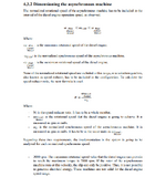
In the steady state of this application the asynchronous machine has to act as a generator. Thus, the rotor speed, which is the rotational speed of the diesel engine shaft, has to be bigger than the synchronous speed to achieve a negative slip. (page 30)

The normalized rotational speed of the asynchronous machine has to be included in the interval of the diesel engine operation speed, as observed. (page 31)

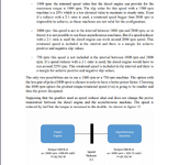
1000 rpm: this speed is not in the interval between 1800 rpm and 2800 rpm, so in theory it is not possible to use these asynchronous machines. But if a speed reducer with a 2:1 ratio is used the diesel engine can work around 2000 rpm speed. This rotational speed is included in the interval and there is a margin for achieve positive and negative slip values.
The option with the less pair of poles (1000 rpm) is chosen in order to have a better power factor. Choosing the 1000 rpm option the product torque∙rotational speed (τ∙ω) is going to be smaller and thus the power dissipated. (page 32)

The nominal power of an asynchronous machine that appears in the nameplate is the result of multiplying the nominal torque by the nominal angular velocity.
However, in the dimensioning of a drive application the parameters that have to be considered are the maximum torque and the normalized synchronism velocity. Multiplying these parameters, the minimum power of the asynchronous machine is obtained. (page 33)
 
Why spend money on a gearbox when you could direct couple to a higher rpm rated motor?
 
I don't want to use a gearbox but the author suggests that to make the speed of the motor to be within the speed range of the engine he has at the maximum torque:

1730831110176.png
1730831707368.png
 

Part and Inventory Search

Sponsor